NetClock/GTP Instruction Manual
Page 5-1
SERVICE INFORMATION
5.0 INTRODUCTION
This section provides information on troubleshooting GPS reception problems
and instructions for adjusting the TCXO oscillator.
5.1 RECEPTION
TROUBLESHOOTING
Please review this section prior to calling the Spectracom Customer Service
Department. If the reception problem can not be solved by following the
guidelines outlined in this section, please call for Customer Service at
585-321-5800.
5.1.1 No
Reception
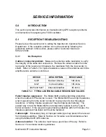
Cable or connector problem
: Measure the antenna cable resistance to verify
the integrity of the cable and connectors. Remove the antenna cable from the
rear panel of the receiver and measure the resistance from the coax center to
shield. Refer to Table 5-1 for typical resistance values of the antenna and inline
amplifier alone and when combined.
DEVICE DESCRIPTION
RESISTANCE
8225
Outdoor Antenna
180 ohms
8227
In-line Amplifier
165 ohms
8225 and 8227
Antenna/Amplifier
85 ohms
TABLE 5-1 TYPICAL ANTENNA CABLE RESISTANCE VALUES
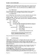
Failed impulse suppressor
: The Model 8226 provides lightning protection
when the outdoor GPS antenna is used. The Model 8226 has a high impedance
when measuring from the center conductor to ground and a low throughput
resistance. A failing impulse suppressor may be tripping prematurely. The
easiest way to test the Model 8226 is to temporarily replace it with a Type N
barrel connector. If the receiver begins tracking satellites within 20 minutes, the
impulse suppressor has failed and must be replaced.
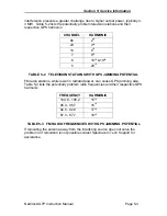
Cable length
: Excessively long or improper cable type may prevent the receiver
from tracking satellites. Refer to Section 2.2 for cable recommendations when
using the Model 8225 GPS Antenna
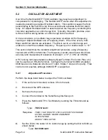
Antenna location
: The antenna must have a good view of the sky. Refer to
Section 2.1 for antenna location guidelines.

