Section 2: Installation
NetClock/GTP Instruction Manual
Page 2-7
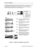
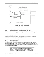
FIGURE 2-6 CABLE GUIDELINES
2.6
NETCLOCK/GTP PREPARATION FOR USE
This section outlines the set-up procedure to prepare the NetClock/GTP for operation.
2.6.1 Antenna
Connection
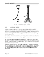
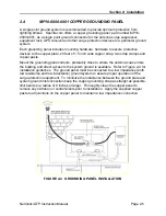
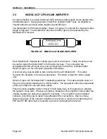
Install the Model 8225 Antenna as outlined previously in this section. Connect the
antenna cable to the rear panel GPS ANTENNA connector.
2.6.2 Power
Connection
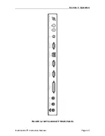
The NetClock/GTP can be powered from a 12 to 36 VDC power source. Power
consumption is 6 Watts. Power is applied to the rear panel banana jacks; Red is for
positive polarity and Black is negative. Place the front panel power switch in the OFF
position before applying power.
Note:
The NetClock/GTP utilizes a locking toggle power
switch. To actuate the switch, first pull on the switch knob,
then move to the desired position ON or OFF, then release.

