Siko IK360 User Manual Download Page 24


IK360 -CAN


x

   Date: 23.01.2017                  Page 24 of 41                    Art.no. 86089                  Mod. Status 10/17 
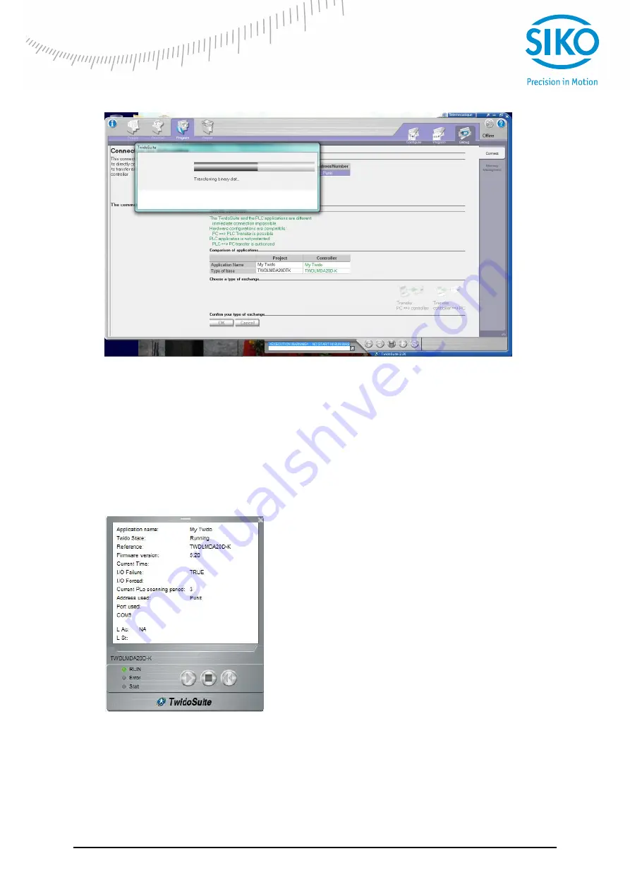


Creating a backu

p of the controller parameters before going into online mode……. 

Once the controller goes into the online mode, the PDOs cannot be changed. But, we can 
program the SDOs as need arises. 


6.5 

Run 

 
Once debugged, the controller goes into online mode. After we can program the SDOs if 
needed and then run the controller. 


Upon start up, we can create an animation table to monitor the necessary controller parameters 
and the system variables, which contain the position value. Now we will program the PLC in 
order to obtain the position values. 


Summary of Contents for IK360

Page 1: ...User manual Inclinometer with CANopen Interface IK360...

Page 2: ...12 5 1 IMPORTANT FACTORY SETTINGS 12 5 2 ACTIVE PROGRAMMING OBJECTS 13 5 3 PROGRAMMABLE PARAMETERS 13 5 4 PDO TRANSMISSION 14 5 5 EXPLICIT EXCHANGES SDO 17 6 WORKING WITH SCHNEIDER PLC 18 6 1 INTRODU...

Page 3: ...T 3002H TERMINATION RESISTOR 35 8 23 OBJECT 3022H DIGITAL RECURSIVE FILTER 35 8 24 OBJECT 3100H MOVING AVERAGE FILTER 35 8 25 OBJECT 6000H RESOLUTION 35 8 26 OBJECT 6010H SLOPE LONG16 36 8 27 OBJECT 6...

Page 4: ...abel indicates that an electrical hazard exists which will result in personal injury if the instructions are not followed This is the safety alert symbol It is used for alerting in case of potential p...

Page 5: ...nd is nowadays used in many industrial applications The application protocol CANopen was introduced by the multi vendor association CAN in Automation CiA to ensure a full compatibility of industrial a...

Page 6: ...ftware filters Other functions such as offset values baud rate and node number can also be configured using CANopen objects in the IK360 inclinometers with ease and according to the network Various so...

Page 7: ...on receiving the corresponding indication Stopped on receiving the Stop Remote Node NMT indication Operational on receiving the Start Remote Node NMT indication To set one or all nodes to pre operati...

Page 8: ...00h NMT Reset Node 0h 81h NN in hex NMT Reset Node NN node number After reinitialization the inclinometer accesses the bus in pre operational mode 3 1 5 Reset communication of the inclinometer If the...

Page 9: ...ld not answer after each SYNC telegram on the CAN network the parameter sync counter can be programmed to skip a certain number of sync telegrams before answering again 3 3 Boot up procedure The gener...

Page 10: ...ion The mounting surface must be plane and free of dust and grease It is absolutely necessary that the IK360 inclinometer is connected to potential equalization in a workmanlike manner For mounting we...

Page 11: ...ck into the CAN bus The bus wires can be routed in parallel twisted or shielded form in accordance with the electromagnetic compatibility requirements A single line structure minimizes reflection The...

Page 12: ...ethodology is described for putting the IK360 into operation and in the second part the PDO SDO programming of IK360 5 1 Important factory settings Description Object Value Device Type 1000h 0 x 3019A...

Page 13: ...t 43h 4Bh 4Fh SDO Download Reply Parameter to Master 80h Warning Reply Transmission error Table 1 Command description The value of the command byte depends on the data length of the called parameter s...

Page 14: ...The baud rate can be programmed via SDO Filter Objects 3100h 3022h Filter can be used to adjust the frequency of measurements and calculation of position values Object 3100h corresponds to moving aver...

Page 15: ...ication parameter of the 2nd transmit PDO Subindex Description Data Type Default Value Access Restore after BootUp 00h Number of sub indices Unsigned 8 5 ro yes 01h COB ID Unsigned 32 280h Node ID rw...

Page 16: ...of the object 1800 or 1801 The data transfer also takes place with no change to data The range is between 1 65536 ms Cyclic Timer The cyclic timer is useful to set the position transmission to cyclic...

Page 17: ...has been updated the client returns a confirmation message For an unprocessed SDO In both cases if a SDO could not be processed the device master returns an error code A typical illustration of SDO fo...

Page 18: ...connected to a TWIDO programmable logic controller with a CANopen communication interface The step by step connection procedure and the working of inclinometer in a CAN bus is illustrated in the follo...

Page 19: ...tatus 10 17 Hardware setup and wiring 6 2 2 Software project information Once the hardware setup is done the IK360 should be configured in such a way that it is compatible to the already existing setu...

Page 20: ...ustration below describes the connection of the elements in the CAN bus At first the CANopen communication interface is connected to the main controller Then the inclinometer is connected to the CANop...

Page 21: ...e bus and click on Configuration A list of all the mapped PDOs appear Then according to the need the objects are mapped on to the Transmit PDOs of the IK360 IK360 CANopen node configuration Click at t...

Page 22: ...60 Transmit PDOs Select the CANopen link of the controller Click on the configuration option The PDOs of the slave are mapped on the CANopen master so that the information contained in the objects at...

Page 23: ...DOs It involves the following steps The serial communication port is selected and PC controller transfer is initiated Once the transfer is initiated the configured parameters and the programming done...

Page 24: ...annot be changed But we can program the SDOs as need arises 6 5 Run Once debugged the controller goes into online mode After we can program the SDOs if needed and then run the controller Upon start up...

Page 25: ...IK360 CAN x Date 23 01 2017 Page 25 of 41 Art no 86089 Mod Status 10 17 Resetting CANopen communication Resetting CANopen nodes Switch to operational mode Position readout position value...

Page 26: ...10 17 Readout using animation table Illustration of measurement over full range At initial position approximately 0 IK360 position value 32 0 01 0 32 At approximately 90 IK360 position value 9138 0 01...

Page 27: ...inometer doesn t respond Problem If the bus is active than the installed inclinometer is transmitting a false node number If the bus is inactive then it was connected with an incorrect baud rate Possi...

Page 28: ...ber change fed to it in order to avoid the node number 0 2 For example If we want a Node Number 28 dec we need to feed 27 decimal 27 1 28 So the Node Number 1B hex has to be fed in order to set the se...

Page 29: ...device and have been signaled via the Emergency object The error code is located in the least significant word and additional information is located in the most significant word Subindex 0 contains t...

Page 30: ...cess Restore after BootUp 0 Unsigned 16 0 rw yes 8 9 Object 100Dh Life Time Factor This object contains the life time factor parameters The life time factor multiplied with the guard time gives the li...

Page 31: ...nsigned 32 rw no 2 Restore communication parameters Unsigned 32 rw no 3 Restore application parameters Unsigned 32 rw no 4 Restore manufacture parameters Unsigned 32 rw no Storing procedure To load th...

Page 32: ...bindex 1 is as follows Bit 31 to 24 23 to 16 15 to 0 Value 0h reserved Address of monitored device Monitoring time ms 8 14 Object 1017h Producer Heartbeat Time The object contains the time interval in...

Page 33: ...o no 8 18 Object 2600h Preset X Axis IK360 2 axis Preset IK360 1 axis In IK360 1 axis inclinometers this object sets the X axis to a desired value In IK360 2 axis inclinometers this object sets the Z...

Page 34: ...ins the node number of the device The standard node number is 1h Subindex Description Data Type Default Value Access Restore after BootUp 0 Node Number Unsigned 8 0 rw yes Note To avoid the node numbe...

Page 35: ...al Recursive Filter This particular object controls the weighting factor of the recursive filter If set to 0 the filter is deactivated Valid values range from 0 to 1000 The value specifies the weighti...

Page 36: ...If bit 1 is set slope long16 offset and differential slope long16 offset are added to the slope long16 Both bits can be at the same time Subindex Description Data Type Default Value Access Restore af...

Page 37: ...tion Data Type Default Value Access Restore after BootUp 0 Offset Value Integer 16 rw no The main difference between the objects 6013h and 6014h is that 6013h is calculated automatically depending on...

Page 38: ...within the range of the position value limits Subindex Description Data Type Default Value Access Restore after BootUp 0 Preset Value Integer 16 00 rw no Resolution Preset Range in decimal Type IK360...

Page 39: ...only if scaling of slope long16 is enabled Please note that the values sholud be within the range of position attribute according to the resolution already set Subindex Description Data Type Default V...

Page 40: ...IK360 CAN x Date 23 01 2017 Page 40 of 41 Art no 86089 Mod Status 10 17 IK360 2 axis X Achse Output Value Resolution 0 01 IK360 2 axis Y Achse Output Value Resolution 0 01...

Page 41: ...object The COB ID consists of a function code and a node number N NMT Network management object This is responsible for managing the execution configuration and errors in a CAN network NN Node number...

Reviews: