


IK360 -CAN
x
Date: 23.01.2017 Page 18 of 41 Art.no. 86089 Mod. Status 10/17
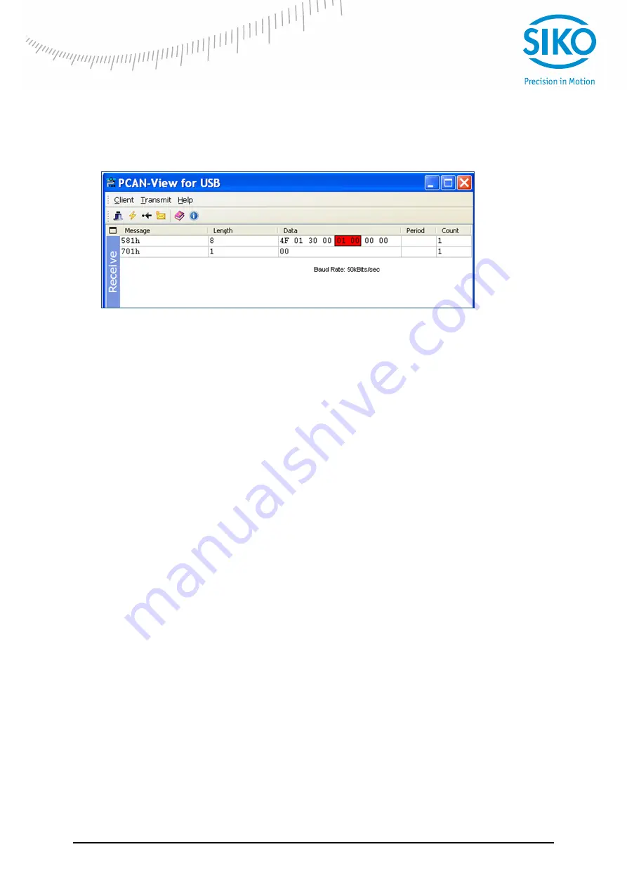
The received message
ID: 581h - message from node number 1
Data 0: length of data is 1 byte
Data 4-7: 01 equates 50 kBaud/s
Received Message from the device
So, SDOs can be used to explicitly read or write data in IK360. All the relevant objects, that can
be configured, are described in Appendix A.
In the above example 701h is the boot up message received. Then once we transmit the SDO
command as shown above, we receive a reply. The received message, 581h, consists of the
SDO downloaded.
6
Working with Schneider PLC
6.1
Introduction
An IK360, single axis inclinometer was connected to a TWIDO programmable logic controller
with a CANopen communication interface.
The step-by-step connection procedure and the working of inclinometer in a CAN bus is
illustrated in the following sections. Please note, that the programming in other control systems
may vary individually. Please have this section as a reference for IK360's working with
programmable logic controllers.
6.2
Network initialization
6.2.1
Hardware
The initial step in setting up an IK360 is integrating it into the existing hardware. The following
illustration shows an IK360 integrated into a PLC with an CANopen communication interface.
It is very important to add termination resistors to the IK360, which are used at the start or end
of the CANopen bus in order to prevent data corruption or missing of data at higher
transmission bandwidths (
≥50 kB).