


Component
Order number
Photo
Hot swappable
1
Foam insert set for wall mount with
connectors
A5E38287828
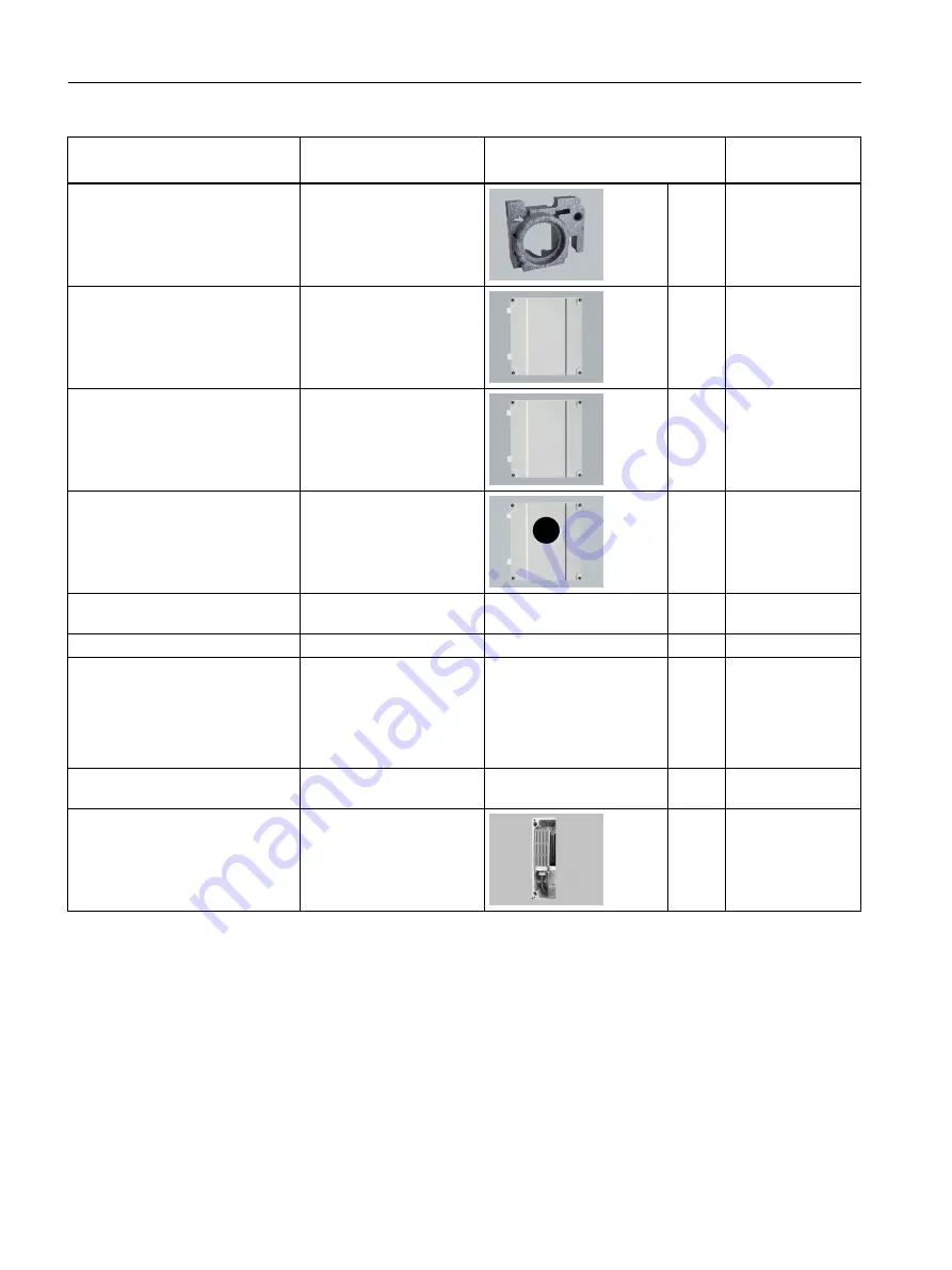
Wall mount enclosure front, blind,
Siemens version
A5E38287882
Wall mount enclosure front, blind,
Neutral version - no company logo
A5E38287965
Wall mount enclosure front w. glass A5E38288007
Wall mount enclosure bracket for
pipe mounting
A5E38288020
Wall bracket panel mounting
A5E38288032
Bag of loose spare parts for wall
mount including cable strain relief
components, mounting tool, seals
and gasket. Assorted screws and
washers, hex cap nut, blind plugs,
and O-rings
A5E38288072
Metal Kit: PSU cover back pane for
Wall mount enclosure
A5E38415145
Power input cover plate for wall
mount enclosure
A5E38415205
1. Components may be replaced while power is on
Service and maintenance
9.8 Spare parts/Accessories
FC430 (From firmware 4.0)
196
Operating Instructions, 06/2017, A5E39789392-AA


