I-T-E Connecting Studs (RS5785, RS5786)
1 9
General
These connecting studs can be used on 3-pole circuit
breakers and on line and load terminals. Both the long stud
RS5785 and the short stud RS5786, can be used on adjacent
poles or alternated, as required by the installation.
Connecting Studs Attached To Breaker
Mounting Preparation
A.
Turn off and lock out all power supplying circuit breaker
before installing.
B.
Drill mounting panel as shown in drilling plan, Figure 1.
This user provided panel must be made from a material
acceptable for supporting uninsulated live parts and
have adequate strength to support the circuit breaker.
Thickness should be 1/4 in. min. and 1 in. max.
C.
Figures 1 and 2 show dimensioning information which
can be used to plan the circuit breaker termination
interface.
Figure 1
Figure 2
Summary of Contents for I-T-E Sensitrip MD Series
Page 2: ......
Page 6: ...4 I T E Sensitrip Digital Circuit Breaker MD and ND Frame Outline Drawings 1 3 Pole ...
Page 8: ...6 MD and ND Frame Trip Adjustments ...
Page 12: ...10 MD and ND Frame Time Current Curve 600 1000A With Short Time Delay Set on Fixed Time ...
Page 13: ...MD and ND Frame Time Current Curve 11 1200A With Short Time Delay Set on Fixed Time ...
Page 14: ...12 MD and ND Frame Time Current Curve 600 100A With Short Time Delay Set on I2 t ...
Page 15: ...MD and ND Frame Time Current Curve 13 1200A With Short Time Delay Set on I2 t ...
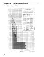
Page 16: ...14 MD and ND Frame Time Current Curve 600 100A Without Short Time Settings ...
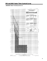
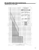
Page 17: ...MD and ND Frame Time Current Curve 15 1200A Without Short Time Settings ...
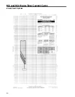
Page 18: ...16 MD and ND Frame Time Current Curve Ground Fault Trip Data ...
Page 19: ...MD and ND Frame Time Current Curve 17 Example ...
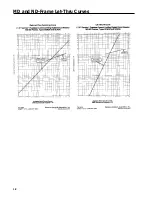
Page 20: ...18 MD and ND Frame Let Thru Curves ...
Page 31: ...Installation Diagrams 29 ...
Page 35: ...I T E Mechanical Interlock M15404 33 Figure 7 ...
Page 41: ...Installation Diagrams 39 ...
Page 49: ...Installation Diagrams 47 ...
Page 50: ...48 I T E Panelboard Connecting Straps 1 ...
Page 53: ...Installation Diagrams 51 ...


