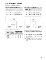
I-T-E Internal Accessories
35
Figure 3
C.
Check handle for proper fit on handle arm. Replace load
end cover and cover screws. (quantity 8)
Replace All Covers and Shields
A.
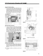
Add two labels to circuit breaker Attach internal acces-
sory ID label (16) (Figure 4) to top of circuit breaker on right
hand side. Make sure it is located in the proper space on
existing label. Attach wiring label (17) on side of circuit
breaker cover as shown
NOTE: This accessory is suitable to use for Ground Fault
Protection when combined with Class I Ground Fault
Sensing Element equipped with internal clearing switch .
Figure 4
Summary of Contents for I-T-E Sensitrip MD Series
Page 2: ......
Page 6: ...4 I T E Sensitrip Digital Circuit Breaker MD and ND Frame Outline Drawings 1 3 Pole ...
Page 8: ...6 MD and ND Frame Trip Adjustments ...
Page 12: ...10 MD and ND Frame Time Current Curve 600 1000A With Short Time Delay Set on Fixed Time ...
Page 13: ...MD and ND Frame Time Current Curve 11 1200A With Short Time Delay Set on Fixed Time ...
Page 14: ...12 MD and ND Frame Time Current Curve 600 100A With Short Time Delay Set on I2 t ...
Page 15: ...MD and ND Frame Time Current Curve 13 1200A With Short Time Delay Set on I2 t ...
Page 16: ...14 MD and ND Frame Time Current Curve 600 100A Without Short Time Settings ...
Page 17: ...MD and ND Frame Time Current Curve 15 1200A Without Short Time Settings ...
Page 18: ...16 MD and ND Frame Time Current Curve Ground Fault Trip Data ...
Page 19: ...MD and ND Frame Time Current Curve 17 Example ...
Page 20: ...18 MD and ND Frame Let Thru Curves ...
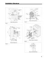
Page 31: ...Installation Diagrams 29 ...
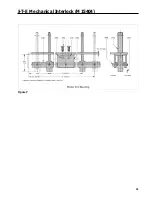
Page 35: ...I T E Mechanical Interlock M15404 33 Figure 7 ...
Page 41: ...Installation Diagrams 39 ...
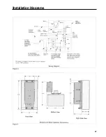
Page 49: ...Installation Diagrams 47 ...
Page 50: ...48 I T E Panelboard Connecting Straps 1 ...
Page 53: ...Installation Diagrams 51 ...


