I-T-E Connecting Studs (RS5785, RS5786)
2 1
F
Remove the positioning template.
G.
Mount the circuit breaker by positioning it over the rear
busbar mounting pads. Attach each pole (Line and
Load) of the circuit breaker to the connecting busbars
with the two 5/16-18 hex head cap screws, flatwashers
and lockwashers (4) (Figure 4). Torque each screw to 72
in. lb.
H.
Insert the end shields (7) into the slots provided at the line
and load ends of the breaker (Figure 4).
I.
Replace the breaker terminal shields, (1) on the line and
load side of the circuit breaker and secure with four
breaker terminal shield screws (2). Tighten to 12 in. lb.
(Figure 3).
J.
Affix label (8) (This device is equipped with rear connect-
ing studs) to the front of the circuit breaker (Figure 3).
Figure 6
Summary of Contents for I-T-E Sensitrip MD Series
Page 2: ......
Page 6: ...4 I T E Sensitrip Digital Circuit Breaker MD and ND Frame Outline Drawings 1 3 Pole ...
Page 8: ...6 MD and ND Frame Trip Adjustments ...
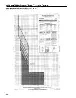
Page 12: ...10 MD and ND Frame Time Current Curve 600 1000A With Short Time Delay Set on Fixed Time ...
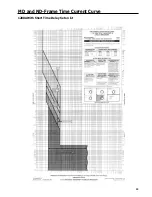
Page 13: ...MD and ND Frame Time Current Curve 11 1200A With Short Time Delay Set on Fixed Time ...
Page 14: ...12 MD and ND Frame Time Current Curve 600 100A With Short Time Delay Set on I2 t ...
Page 15: ...MD and ND Frame Time Current Curve 13 1200A With Short Time Delay Set on I2 t ...
Page 16: ...14 MD and ND Frame Time Current Curve 600 100A Without Short Time Settings ...
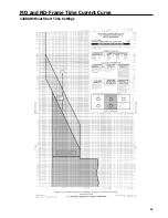
Page 17: ...MD and ND Frame Time Current Curve 15 1200A Without Short Time Settings ...
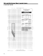
Page 18: ...16 MD and ND Frame Time Current Curve Ground Fault Trip Data ...
Page 19: ...MD and ND Frame Time Current Curve 17 Example ...
Page 20: ...18 MD and ND Frame Let Thru Curves ...
Page 31: ...Installation Diagrams 29 ...
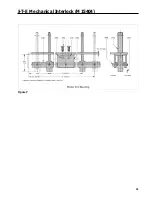
Page 35: ...I T E Mechanical Interlock M15404 33 Figure 7 ...
Page 41: ...Installation Diagrams 39 ...
Page 49: ...Installation Diagrams 47 ...
Page 50: ...48 I T E Panelboard Connecting Straps 1 ...
Page 53: ...Installation Diagrams 51 ...


