44
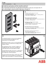
I-T-E Max-Flex
TM
Flange-Mount Handle Operator
Cable Adjustment
A.
Check that the circuit breaker turns OFF and ON by
moving the operating handle up for ON and down for OFF
If the breaker does not switch ON, loosen the cable
mounting nuts at the fixed plate tab. Hold the operating
handle in the maximum ON position and move the cable
toward the top of the breaker. Retighten the mounting
nuts to secure.
B.
Trip the circuit breaker by pushing the PUSH TO TRIP
button
C.
Check that the circuit breaker resets by moving the
operating handle from ON to OFF and back to ON. If the
breaker resets, tighten the spring adjuster one additional
turn. Attach lockwashers and 1/4-28 nut to the end of the
cable rod and tighten to 32 in. Ib.
D.
If the circuit breaker does not reset, tighten the spring
adjusters one turn and repeat Steps B and C. Continue
this procedure until the breaker resets then tighten the
adjusters one additional turn and secure with lockwashers
and nut.
Spring Adjustment
Cable Adjustment
Side View of Handle Assembly
Summary of Contents for I-T-E Sensitrip MD Series
Page 2: ......
Page 6: ...4 I T E Sensitrip Digital Circuit Breaker MD and ND Frame Outline Drawings 1 3 Pole ...
Page 8: ...6 MD and ND Frame Trip Adjustments ...
Page 12: ...10 MD and ND Frame Time Current Curve 600 1000A With Short Time Delay Set on Fixed Time ...
Page 13: ...MD and ND Frame Time Current Curve 11 1200A With Short Time Delay Set on Fixed Time ...
Page 14: ...12 MD and ND Frame Time Current Curve 600 100A With Short Time Delay Set on I2 t ...
Page 15: ...MD and ND Frame Time Current Curve 13 1200A With Short Time Delay Set on I2 t ...
Page 16: ...14 MD and ND Frame Time Current Curve 600 100A Without Short Time Settings ...
Page 17: ...MD and ND Frame Time Current Curve 15 1200A Without Short Time Settings ...
Page 18: ...16 MD and ND Frame Time Current Curve Ground Fault Trip Data ...
Page 19: ...MD and ND Frame Time Current Curve 17 Example ...
Page 20: ...18 MD and ND Frame Let Thru Curves ...
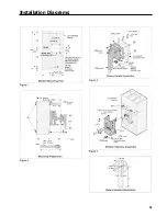
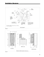
Page 31: ...Installation Diagrams 29 ...
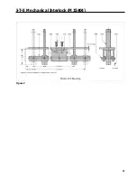
Page 35: ...I T E Mechanical Interlock M15404 33 Figure 7 ...
Page 41: ...Installation Diagrams 39 ...
Page 49: ...Installation Diagrams 47 ...
Page 50: ...48 I T E Panelboard Connecting Straps 1 ...
Page 53: ...Installation Diagrams 51 ...


