2 4
I-T-E Compression Connectors (CCM800, CCN1200)
General
NOTE: This instruction sheet outlines the recommended
installation procedure. Use of lugs may result in reduced
wire bending space. The installer should verify that
adequate wire bending space is still provided for the
installation. in accordance with applicable codes.
Compression Connector Kit - CCN1200
Installation of Compression Connector
A.
Turn off power supplying device before installing com-
pression lugs.
B.
Remove any existing wire connectors from circuit breaker
C.
Install circuit breaker.
D.
Preform cables to final configuration and strip insulation
back 1 13/16 in. on each conductor. Use an appropriate
insulation stripping tool to avoid damaging the conduc-
tor (Figure 1).
E.
Clean aluminum conductor surfaces thoroughly with a
wire brush or other suitable means, to remove oxides
and other contaminants from the conductor.
NOTE: Copper wires and the compression connector should
not be cleaned abrasively.
F
Remove cap from compression connector and insert
cable fully into barrel (1) (Figure 1 ) of connector.
G.
Insure that connector tang(s) (2) (Figure 1) are in their
proper orientation prior to crimping. This helps avoid
twisting of cables during installation.
Figure 1
H.
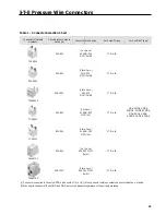
Select an appropriate tool and die combination from
Table 1 and make the required number of crimps within
the boundaries stamped on the connector barrel. Refer
to Figure 2 for sequence of multiple crimps.
Figure 2
I.
Remove any inhibitor compound expelled during the
crimping operation from the connector body and the
cable insulation .
J.
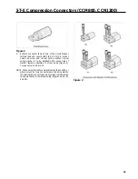
Slip insulating cover over connector tang and then over
connector barrel so that only the connector tang is ex-
posed (Figure 3).
WARNING:
Short spacings will result if Step J is not followed.
Summary of Contents for I-T-E Sensitrip MD Series
Page 2: ......
Page 6: ...4 I T E Sensitrip Digital Circuit Breaker MD and ND Frame Outline Drawings 1 3 Pole ...
Page 8: ...6 MD and ND Frame Trip Adjustments ...
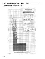
Page 12: ...10 MD and ND Frame Time Current Curve 600 1000A With Short Time Delay Set on Fixed Time ...
Page 13: ...MD and ND Frame Time Current Curve 11 1200A With Short Time Delay Set on Fixed Time ...
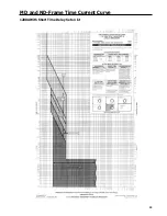
Page 14: ...12 MD and ND Frame Time Current Curve 600 100A With Short Time Delay Set on I2 t ...
Page 15: ...MD and ND Frame Time Current Curve 13 1200A With Short Time Delay Set on I2 t ...
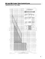
Page 16: ...14 MD and ND Frame Time Current Curve 600 100A Without Short Time Settings ...
Page 17: ...MD and ND Frame Time Current Curve 15 1200A Without Short Time Settings ...
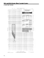
Page 18: ...16 MD and ND Frame Time Current Curve Ground Fault Trip Data ...
Page 19: ...MD and ND Frame Time Current Curve 17 Example ...
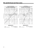
Page 20: ...18 MD and ND Frame Let Thru Curves ...
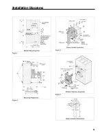
Page 31: ...Installation Diagrams 29 ...
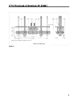
Page 35: ...I T E Mechanical Interlock M15404 33 Figure 7 ...
Page 41: ...Installation Diagrams 39 ...
Page 49: ...Installation Diagrams 47 ...
Page 50: ...48 I T E Panelboard Connecting Straps 1 ...
Page 53: ...Installation Diagrams 51 ...


