3M Dynatel 2250M Series, Operator'S Manual
The 3M Dynatel 2250M Series Operator's Manual is a comprehensive guide for users of this advanced product. Available for free download on our website, it provides detailed instructions and valuable insights to ensure optimum performance. Discover enhanced functionalities and troubleshooting techniques, exclusively from our manualshive.com.
Share
Download


Reviews:
No comments
Related manuals for Dynatel 2250M Series

NB1-63H/2
Brand: CHINT Pages: 10

SE-BD DTV3 Series
Brand: OEZ Pages: 12

HT7
Brand: HT Pages: 16

9083P
Brand: Di-LOG Pages: 31

SignalTEK CT
Brand: IDEAL Networks Pages: 74

NDM3Z Series
Brand: nader Pages: 33

CT3686
Brand: Cal Test Pages: 16

Tmax T8 L5757
Brand: ABB Pages: 39

MS6813
Brand: Mastech Pages: 14

HD4 Series
Brand: ABB Pages: 44
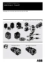
SACE Emax 2
Brand: ABB Pages: 10


