42
I-T-E Max-Flex
TM
Flange-Mount Handle Operator
Types 1, 3R, 4, 4X, 12
D.
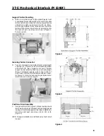
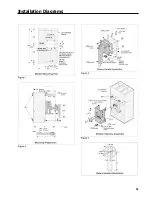
Place the plastic washer and connecting link onto the
bellcrank pin (7). Secure the connection with the E-ring
retainer supplied (8) (Figure 3).
Secure E-Ring Connection
E.
Attach the interlock level extension (9) to the interlock
lever using two #8-32-3/s in. screws and #8 lockwashers.
Screws mount through the threaded lever extension into
the lever Tighten to 25 in.-lb. (Figure 3).
Operating Note:
When the enclosure door is open, the operating handle
cannot be moved from the OFF to ON position without
deliberately defeating the interlock mechanism. In the OFF
position, the interlock can be defeated by pushing the inter-
lock lever extension downward while moving the handle to the
ON position. With the enclosure door open and the handle in
the ON position, the interlock can be defeated by turning the
defeater screw (10) (Figure 3) on the operating handle. When
the enclosure door is closed, the door latch mechanism
automatically defeats the interlock.
F
If no door catch is provided with the enclosure, attach the
door catch bracket and adjustable door catch to the
enclosure door.
Door Catch Adjustment
A.
Close the enclosure door and move the handle into the
ON position. If the handle cannot be moved from the ON
position, adjust the door catch downward in its slot and
repeat procedure.
B.
Turn handle ON and attempt to open door. The interlock
should hold the door closed. If the door can be opened,
readjust the door catch upward in its slot. Repeat Steps
A and B to insure the door cannot be opened when the
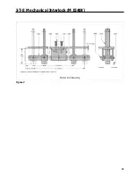
handle is in the ON position. Figure 4 shows the location
of the handle and door catch when mounted in the
enclosure.
Mounting Breaker and Breaker Operator
A.
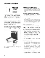
The breaker operator (11 ) is mounted to the circuit
breaker using the same two lower screws (12) that are
used to attach the breaker to the enclosure. In addition,
two #10-32 x 15/s in. screws (13) and spacers are used
at the top and two 1/4-20 X 1/2 in. screws (12) and
spacers are used at the bottom (Figure 5).
Summary of Contents for I-T-E Sensitrip MD Series
Page 2: ......
Page 6: ...4 I T E Sensitrip Digital Circuit Breaker MD and ND Frame Outline Drawings 1 3 Pole ...
Page 8: ...6 MD and ND Frame Trip Adjustments ...
Page 12: ...10 MD and ND Frame Time Current Curve 600 1000A With Short Time Delay Set on Fixed Time ...
Page 13: ...MD and ND Frame Time Current Curve 11 1200A With Short Time Delay Set on Fixed Time ...
Page 14: ...12 MD and ND Frame Time Current Curve 600 100A With Short Time Delay Set on I2 t ...
Page 15: ...MD and ND Frame Time Current Curve 13 1200A With Short Time Delay Set on I2 t ...
Page 16: ...14 MD and ND Frame Time Current Curve 600 100A Without Short Time Settings ...
Page 17: ...MD and ND Frame Time Current Curve 15 1200A Without Short Time Settings ...
Page 18: ...16 MD and ND Frame Time Current Curve Ground Fault Trip Data ...
Page 19: ...MD and ND Frame Time Current Curve 17 Example ...
Page 20: ...18 MD and ND Frame Let Thru Curves ...
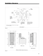
Page 31: ...Installation Diagrams 29 ...
Page 35: ...I T E Mechanical Interlock M15404 33 Figure 7 ...
Page 41: ...Installation Diagrams 39 ...
Page 49: ...Installation Diagrams 47 ...
Page 50: ...48 I T E Panelboard Connecting Straps 1 ...
Page 53: ...Installation Diagrams 51 ...

