Assembly Instructions
43
B.
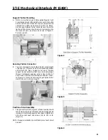
Remove the lower terminal shield (14) from the circuit
breaker and punch and drill out the two .56 in. diameter
knockouts .
C.
Cut slots in terminal shield as shown in Figure 5, to allow
access to terminal lugs after installation of breaker opera-
tor.
Caution:
Replace the terminal shield.
D.
Mount circuit breaker to the enclosed panel using the four
breaker mounting screws as shown in Figure 5.
E.
Attach the breaker operator using two 1/4-20 x 1/2 in.
screws and lockwashers in lower holes and two spacers
and #10-32 x 1s/8 in. screws and lockwashers in upper
holes.
Cable Installation
A.
To attach the operating cable (15) to the frame assembly,
move the operating handle to the OFF position, and
attach the cable swivel (16) to the outer hole in the
bellcrank. Secure the connection with an E-ring. (Figure
6)
B.
Secure the cable to the frame assembly with cable
retainer clip (17) using #10-32 x 3/8 in. screws and
lockwashers. Tighten to 75 in. Ib.
NOTE: Detent in cable retainer (17) must align with groove (18)
in metal fitting of cable (Figure 6).
Tighten Detent Screws
C.
Prior to attaching output end of cable to handle frame,
confirm that supply power to the circuit breaker has been
turned off.
D.
Move circuit breaker handle to the ON position.
E.
Slide the threaded cable rod (19) through the hole in the
sliding plate tab (20) of the circuit breaker operating
mechanism (Figures 5 and 6).
F.
Move the operating handle to its maximum ON position.
G.
Place the cable mounting threads (21 ) into the slot on the
fixed plate tab (22) so that the two mounting nuts (23) are
on both sides of the tab. Adjust the two mounting nuts so
that the #10-32 nut on the cable rod just touches the
sliding plate tab. Tighten the mounting nuts to secure the
cable (Figures 5 and 6).
H.
Continue holding the operating handle in the ON position
and place the spring (24) over the end of the rod. Screw
on the spring adjuster (25) and tighten until it begins to
compress the spring. DO NOT OVERTIGHTEN THE
SPRING ADJUSTMENT NUT
Summary of Contents for I-T-E Sensitrip MD Series
Page 2: ......
Page 6: ...4 I T E Sensitrip Digital Circuit Breaker MD and ND Frame Outline Drawings 1 3 Pole ...
Page 8: ...6 MD and ND Frame Trip Adjustments ...
Page 12: ...10 MD and ND Frame Time Current Curve 600 1000A With Short Time Delay Set on Fixed Time ...
Page 13: ...MD and ND Frame Time Current Curve 11 1200A With Short Time Delay Set on Fixed Time ...
Page 14: ...12 MD and ND Frame Time Current Curve 600 100A With Short Time Delay Set on I2 t ...
Page 15: ...MD and ND Frame Time Current Curve 13 1200A With Short Time Delay Set on I2 t ...
Page 16: ...14 MD and ND Frame Time Current Curve 600 100A Without Short Time Settings ...
Page 17: ...MD and ND Frame Time Current Curve 15 1200A Without Short Time Settings ...
Page 18: ...16 MD and ND Frame Time Current Curve Ground Fault Trip Data ...
Page 19: ...MD and ND Frame Time Current Curve 17 Example ...
Page 20: ...18 MD and ND Frame Let Thru Curves ...
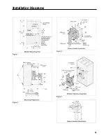
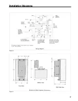
Page 31: ...Installation Diagrams 29 ...
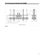
Page 35: ...I T E Mechanical Interlock M15404 33 Figure 7 ...
Page 41: ...Installation Diagrams 39 ...
Page 49: ...Installation Diagrams 47 ...
Page 50: ...48 I T E Panelboard Connecting Straps 1 ...
Page 53: ...Installation Diagrams 51 ...


