MD and ND-Frame Trip Adjustments
9
Figure 1
I
n
= Maximum circuit breaker ampere rating.
I
r
= Current Rating—a function of continuous ampere adjust-
ment setting expressed in % of I
n
Adjustable Instantaneous Trip Switch
x I
r
Instantaneous settings are multiples of the continuous cur-
rent setting.
NOTE: Maximum instantaneous trip is 10,000 Amps—with
instantaneous setting on “MAX”, time delay is eliminated.
I
g
= Ground Fault Pickup—a function of adjustment setting
expressed in % of I
n
.
Adjustable Ground Fault Pickup
Pickup I
g
=%I
n
Delay 1
2
t @ 51n
Ground fault protection is available for 3 phase, 3 wire and 3
phase 4 wire (neutral) electrical systems. SMD/SND models
with an adjustable ground fault delay switch allow for the
selection of ground fault pickup at 20, 25, 30, 40, 55 or 70%
of the maximum amps rating (%I
n
), with an 1
2
t delay of .1, .2,
or .4 sec @ .5 x I
n
See Figure 1 for possible settings for this
switch
Summary of Contents for I-T-E Sensitrip MD Series
Page 2: ......
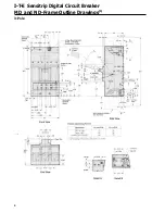
Page 6: ...4 I T E Sensitrip Digital Circuit Breaker MD and ND Frame Outline Drawings 1 3 Pole ...
Page 8: ...6 MD and ND Frame Trip Adjustments ...
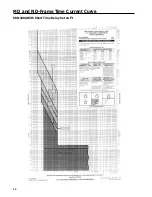
Page 12: ...10 MD and ND Frame Time Current Curve 600 1000A With Short Time Delay Set on Fixed Time ...
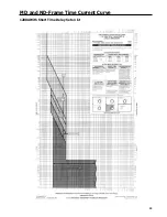
Page 13: ...MD and ND Frame Time Current Curve 11 1200A With Short Time Delay Set on Fixed Time ...
Page 14: ...12 MD and ND Frame Time Current Curve 600 100A With Short Time Delay Set on I2 t ...
Page 15: ...MD and ND Frame Time Current Curve 13 1200A With Short Time Delay Set on I2 t ...
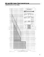
Page 16: ...14 MD and ND Frame Time Current Curve 600 100A Without Short Time Settings ...
Page 17: ...MD and ND Frame Time Current Curve 15 1200A Without Short Time Settings ...
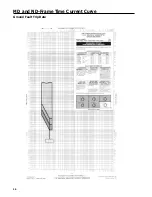
Page 18: ...16 MD and ND Frame Time Current Curve Ground Fault Trip Data ...
Page 19: ...MD and ND Frame Time Current Curve 17 Example ...
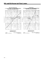
Page 20: ...18 MD and ND Frame Let Thru Curves ...
Page 31: ...Installation Diagrams 29 ...
Page 35: ...I T E Mechanical Interlock M15404 33 Figure 7 ...
Page 41: ...Installation Diagrams 39 ...
Page 49: ...Installation Diagrams 47 ...
Page 50: ...48 I T E Panelboard Connecting Straps 1 ...
Page 53: ...Installation Diagrams 51 ...


