I-T-E TELEMAND
®
Electric Motor Operator
45
General
The motor operated mechanism is designed to open, close
and reset a circuit breaker or switch by remote control. The
customer must supply the circuit breaker or switch normally
ON and OFF push buttons, external wiring, a control power
source, and all control logic. Consult the wiring diagram
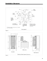
(Figure 3, page 47) for a typical control connection.
The motor operator is hinged for opening to the left or right
dependent on catalog number designation. The “L” suffix
means the motor operator is hinged to the left. A motor
operator hinged to the right uses no suffix.
NOTE: For automatic reset operation a separate auxiliary
contact must be provided by the customer. See page for
more details.
Operator Selection
AAAA
AAAA
AAAA
AAAA
AAAA
AAAA
AAAA
AAAA
AAAA
AAAA
AAAA
AAAA
AAA
AAA
AAA
AAA
AAAA
AAAA
AAAA
AAAA
AAAA
AAAA
AAAA
AAAA
AAAA
AAAA
AAAA
AAAA
AAAA
AAAA
AAAA
AAAA
Motor
Operator
Frame
For Use With: I-T-E Circuit
Breakers and Switch Types
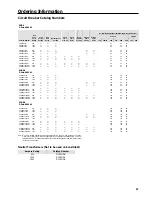
MOMN6120
MOMN6120L
MOMN6240
MOMN6240L
MD, ND
MD6, HMD6 CMD6 SMD6
SHMD6 SCMD6, ND6, HND6,
CND6 SND6, SHND6, SCND6,
MD6-ETI. CMD6-ETI
Installation
A.
Turn off and lock out all power supplying circuit breaker
and motor operator before installing or servicing.
B.
Attach the circuit breaker to its mounting surface using
the mounting hardware (1) supplied with the motor
operator (Figure 2).
C.
Remove the four shield screws (2) and two lug shields (3)
(Figure 1).
D.
Cut out the two 0.563 in. x 1.44 in. long knockouts and
replace the shields.
E.
Open the motor operator cover and attach the motor
operator to the circuit breaker using the spacers (4) and
screws (5) provided (Figure 2).
Summary of Contents for I-T-E Sensitrip MD Series
Page 2: ......
Page 6: ...4 I T E Sensitrip Digital Circuit Breaker MD and ND Frame Outline Drawings 1 3 Pole ...
Page 8: ...6 MD and ND Frame Trip Adjustments ...
Page 12: ...10 MD and ND Frame Time Current Curve 600 1000A With Short Time Delay Set on Fixed Time ...
Page 13: ...MD and ND Frame Time Current Curve 11 1200A With Short Time Delay Set on Fixed Time ...
Page 14: ...12 MD and ND Frame Time Current Curve 600 100A With Short Time Delay Set on I2 t ...
Page 15: ...MD and ND Frame Time Current Curve 13 1200A With Short Time Delay Set on I2 t ...
Page 16: ...14 MD and ND Frame Time Current Curve 600 100A Without Short Time Settings ...
Page 17: ...MD and ND Frame Time Current Curve 15 1200A Without Short Time Settings ...
Page 18: ...16 MD and ND Frame Time Current Curve Ground Fault Trip Data ...
Page 19: ...MD and ND Frame Time Current Curve 17 Example ...
Page 20: ...18 MD and ND Frame Let Thru Curves ...
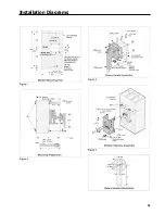
Page 31: ...Installation Diagrams 29 ...
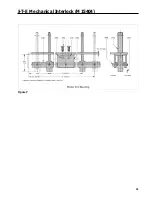
Page 35: ...I T E Mechanical Interlock M15404 33 Figure 7 ...
Page 41: ...Installation Diagrams 39 ...
Page 49: ...Installation Diagrams 47 ...
Page 50: ...48 I T E Panelboard Connecting Straps 1 ...
Page 53: ...Installation Diagrams 51 ...

