MD and ND-Frame Trip Adjustments
7
Figure 1
I
n
= Maximum circuit breaker ampere rating.
I
r
= Current Rating—a function of continuous ampere adjust-
ment setting expressed in % of I
n
Adjustable Long Time Delay
Seconds @ 6 x I
r
SMD/SND models with an adjustable long time delay switch
allow for selection of long time delays of fixed time intervals
at six times the continuous amps setting (1,). See Figure 1 for
the possible settings for this switch.
I
g
= Ground Fault Pickup—a function of adjustment setting
expressed in % of I
n
.
Adjustable Continuous Amps Switch
I
r
= %I
n
All SMD-SND solid state molded case circuit breakers have
an adjustable continuous amps rating switch. Adjustments
made to this switch can change the continuous amps rating
of the breaker to 20, 30, 40, 50, 60, 70, 80 or 90% of the
maximum continuous amps rating (In) of the circuit breaker.
See Figure 1 for the possible settings for this switch.
Summary of Contents for I-T-E Sensitrip MD Series
Page 2: ......
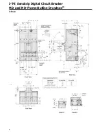
Page 6: ...4 I T E Sensitrip Digital Circuit Breaker MD and ND Frame Outline Drawings 1 3 Pole ...
Page 8: ...6 MD and ND Frame Trip Adjustments ...
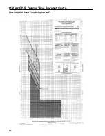
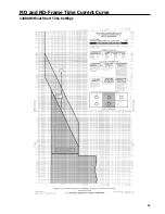
Page 12: ...10 MD and ND Frame Time Current Curve 600 1000A With Short Time Delay Set on Fixed Time ...
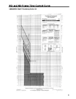
Page 13: ...MD and ND Frame Time Current Curve 11 1200A With Short Time Delay Set on Fixed Time ...
Page 14: ...12 MD and ND Frame Time Current Curve 600 100A With Short Time Delay Set on I2 t ...
Page 15: ...MD and ND Frame Time Current Curve 13 1200A With Short Time Delay Set on I2 t ...
Page 16: ...14 MD and ND Frame Time Current Curve 600 100A Without Short Time Settings ...
Page 17: ...MD and ND Frame Time Current Curve 15 1200A Without Short Time Settings ...
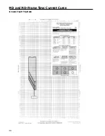
Page 18: ...16 MD and ND Frame Time Current Curve Ground Fault Trip Data ...
Page 19: ...MD and ND Frame Time Current Curve 17 Example ...
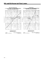
Page 20: ...18 MD and ND Frame Let Thru Curves ...
Page 31: ...Installation Diagrams 29 ...
Page 35: ...I T E Mechanical Interlock M15404 33 Figure 7 ...
Page 41: ...Installation Diagrams 39 ...
Page 49: ...Installation Diagrams 47 ...
Page 50: ...48 I T E Panelboard Connecting Straps 1 ...
Page 53: ...Installation Diagrams 51 ...


