


5
ELECTRICAL INSTALLATION
74
8017768/12AX/2019-05-31|SICK
O P E R A T I N G I N S T R U C T I O N S | TIC
Subject to change without notice
5
Electrical installation
5.1
General advice
DANGER
Disconnect the power to the system
▸
Make sure that all the components of the profiling system are disconnected from the
voltage supply during the electrical installation work.
DANGER
Risk of injury due to electrical current
▸
Comply with standard safety requirements when working on electrical plants.
▸
Be sure to disconnect the voltage supply before attaching or detaching any electrical
connections.
WARNING
Protect cables against slack
▸
Make sure that the cables are routed correctly. The cables must not loop down or fall
slack in any way. They must never pose a hazard to the vehicles driving under the
gantry.
5.2
Connections
All system functions have in common that the system components are connected
individually to the voltage supply and connected to the Traffic Controller via Ethernet.
5.2.1
TIC102 connections
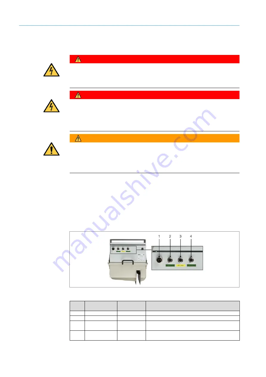
The TIC102 Master has the following connections:
Fig. 78: Connections – TIC102 Master
No.
Connection
Designation
(in diagram)
Description
1
PWR
-X1
Connection to the voltage supply
2
ETH_INTERNAL
-X2
Ethernet connection to a TIC102 Slave
3
ETH_HOST
-X3
Ethernet connection to the network connection
(TEMS Info Interface)
4
ETH_INTERNAL
-X4
Ethernet connection to a TIC102 Slave or the
2D LiDAR sensor for axle counting
Tab. 8: Connections – TIC102 Master
TIC102 master


