CHAPTER 5. SERVICE MENU/VARIOUS SETTING TOOL OPERATING PROCEDURES
PN-T321/T322B
SERVICE MENU/VARIOUS SETTING TOOL OPERATING PROCEDURES
5 – 10
<DRAWING VERTICAL LINES AND COMPENSATION>
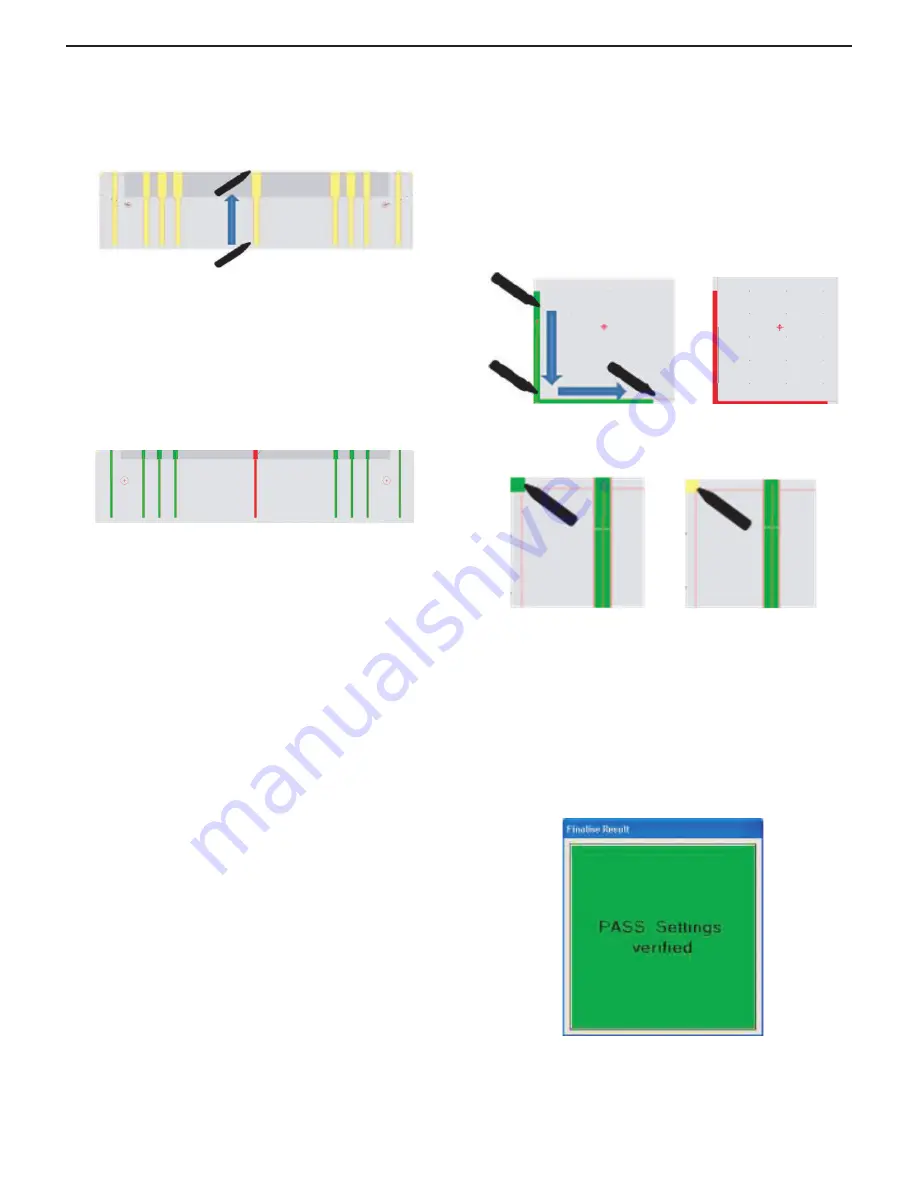
Next, draw vertical lines down to up along 9 yellow lines displayed on
the top of the screen.
Draw slowly not to damage the surface of the glass.
A green square is displayed when the drawing operation is good. (Start-
ing point, end point, and drawing speed are proper). If the drawing oper-
ation isn’t good, a red square is displayed.
In this case, draw a line again and display green square.
If touching an unintentional point because of an operation mistake,
clear all the line track by pressing [C] key of a keyboard and draw lines
again.
After drawing a line to the top of the screen, if the line track is within the
yellow area, the line becomes green. If it isn’t, the line becomes red.
After drawing 9 lines, if a red line is displayed, press [F2] key of the key-
board and do compensation. It takes for some seconds or about 2 min-
utes.
After compensation is finished, do 4 point calibration and drawing 9
lines again.
When a red line is still displayed even if doing compensation, press [F2]
key of the keyboard and do compensation again.
In general case, compensation is converged within 3 times. If a red line
is still displayed, an installation of a camera unit or a reflection frame
might not be proper or a camera unit might have any problem.
Whether doing compensation or not, if all the lines becomes green,
press [F2] key and do compensation, 4 point calibration and drawing 9
lines once again.
<DRAWING 4 CORNERS>
Next, draw lines along the yellow L shaped part displayed at the left/
right bottom of the screen.
At the left bottom of the screen, draw line up
3
down
3
right in that
order. At the right bottom of the screen, draw line up
3
down
3
left in
that order. Please draw slowly not to damage the glass.
If the line track is within the yellow area, the line becomes green. If it
isn’t, the line becomes red.
If a red line is displayed, draw about 5 more times. If a line track is
within the yellow area, the lines changes from red to green.
Finally, touch yellow square displayed at left/right top of the screen.
If it doesn’t result OK, an installation of a camera unit or a reflection
frame might not be proper or a camera unit might have any problem.
(6) FINALISE
After all the part becomes green in Draw Test, Finalization is automati-
cally done and the result of the calibration and the compensation are
saved to the controller boards.
If the result has no problem, the following window is displayed. Click it
and the peration is finished.
After the finalization, a log file is saved to PC.
LOG FILE FOLDER:
\Program Files\NextWindow\USB_Settings_Lite\data
OK
NG
OK
NG


