SEW-Eurodrive MOVIGEAR DAC B Operating Instructions Manual Download Page 17

Operating Instructions – MOVIGEAR® DAC-B 

17

3

MOVIGEAR

®

 electronics

Unit Design

3.6

MOVIGEAR

®

 electronics

3.6.1

MOVIGEAR

®

 electronics cover (inside) and connection box 

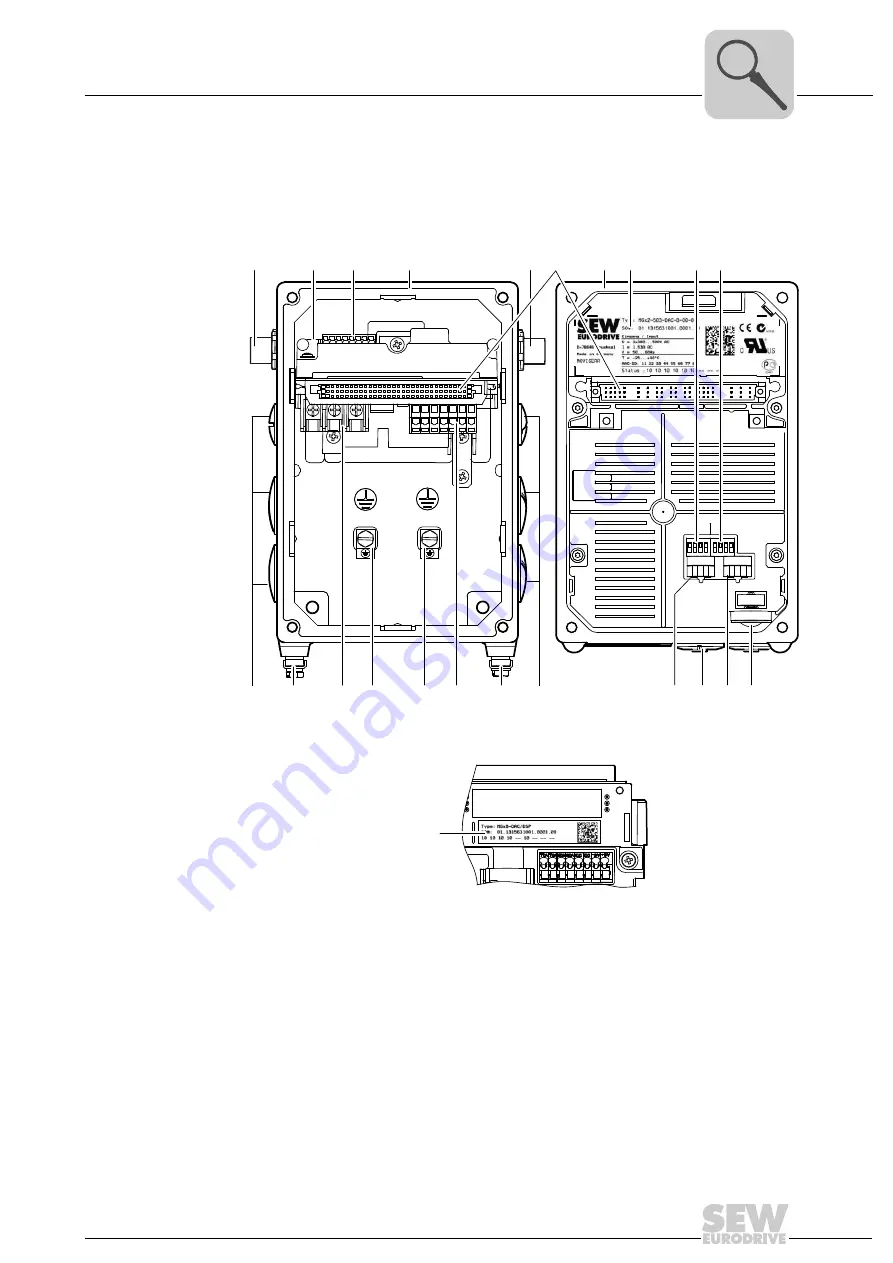
The following figure shows the connection box and the bottom side of the  MOVIGEAR

®

electronics cover:

2366107275

[1]

AS-Interface connection

[2]

Nameplate of drive unit, see following detailed view

2584957963

[3]

AS-Interface terminals (wired to plug connector)

[4]

Connection ring

[5]

AS-Interface sensors

[6]

Plug connector connection unit for MOVIGEAR

®

 electronics cover

[7]

MOVIGEAR

®

 electronics cover

[8]

Electronics cover nameplate

[9]

DIP switches S1/1 – S1/4

[10] DIP switches S2/1 – S2/4
[11] Cable glands 
[12] Screw for PE connection 

[13] Supply system connection L1, L2, L3
[14] Electronics terminal strips
[15] Switch t1 for integrator ramp (green)
[16] Diagnostic interface (below screw fitting)
[17] Setpoint switch f2 (white)
[18] Setpoint potentiometer f1 with screw plug

34567

34567

ON

ADE04SA 

1

2

3

4

ON

ADE04SA 

1

2

3

4

t1

S1

S2

f2 f1

1 2 3 4

1 2 3 4

[3]

[4]

[2]

[1]

[5]

[12]

[11]

[12]

[12]

[12]

[11]

[14]

[13]

[10]

[9]

[6]

[7]

[8]

[15] [16] [17] [18]

[2]

Summary of Contents for MOVIGEAR DAC B

Page 1: ...Drive Technology Drive Automation System Integration Services Operating Instructions Mechatronic Drive System MOVIGEAR DAC B Direct AS Interface Communication Edition 04 2010 16888812 EN...

Page 2: ...SEW EURODRIVE Driving the world...

Page 3: ...4 Position of the cable entry 15 3 5 Sample nameplate and type designation of drive unit 16 3 6 MOVIGEAR electronics 17 3 7 Sample nameplate and type designation for electronics 20 3 8 MOVIGEAR with...

Page 4: ...ing device binary slave GLK30A 92 6 7 Startup with double slave GLK31A 94 6 8 Deactivating DynaStop for startup 101 7 Operation of MOVITOOLS MotionStudio 102 7 1 About MOVITOOLS MotionStudio 102 7 2 F...

Page 5: ...ating hours 198 12 2 Inspection and maintenance intervals 199 12 3 Lubricant change intervals 200 12 4 Inspection and maintenance work on the MOVIGEAR drive 201 13 Technical Data and Dimension Sheets...

Page 6: ...ructions carefully and understood them If you are unclear about any of the information in this documentation or if you require further information contact SEW EURODRIVE 1 2 Structure of the safety not...

Page 7: ...s well as to person who work independently on the unit You must also ensure that the documentation is legible 1 4 Exclusion of liability You must comply with the information contained in the operating...

Page 8: ...ve units can have live bare and movable or rotating parts as well as hot surfaces depending on their enclosure Removing covers without authorization improper use as well as incorrect installation or o...

Page 9: ...You must observe the technical data and information on the connection requirements as provided on the nameplate and in the documentation 2 3 1 Safety functions The MOVIGEAR drive units may not perform...

Page 10: ...is operated as a generator due to the kinetic energy of the plant machine Secure the output shaft against rotation before you open the wiring compartment Electrical installation is to be carried out i...

Page 11: ...voltage because some capacitors might still be charged Wait at least 10 minutes after the supply voltage has been switched off The connection boxes must be closed and screwed on before the supply volt...

Page 12: ...it motor and drive electronics These 3 core components are included in one cast aluminum housing see following figure 2364012555 1 MOVIGEAR electronics cover 2 Connection ring for cable glands 3 Gear...

Page 13: ...he following shaft variants 3 2 1 MOVIGEAR with hollow shaft and keyway MGFA The following figure shows a MOVIGEAR unit with hollow shaft and keyway 3 2 2 MOVIGEAR with TorqLOC hollow shaft mounting s...

Page 14: ...F T The following figure shows the torque arm for MGF T 3 3 2 Housing with threads MGF S The following figure shows the housing type with threads for mounting a torque arm This type does not include a...

Page 15: ...M25 x 1 5 1 x M16 x 1 5 1 x M16 x 1 5 1 2 2 x M25 x 1 5 1 x M16 x 1 5 1 x M16 x 1 5 1 3 2 x M25 x 1 5 2 x M16 x 1 5 Position X 3 X 2 x M25 x 1 5 1 x M16 x 1 5 1 x M16 x 1 5 1 3 2 x M25 x 1 5 2 x M16 x...

Page 16: ...nA A MA Ma pk i Made in Germany IM kg cos IP r min Hz V 13356887 MGFAT2 DSM DAC B DSP 01 1233697403 0001 08 5 4 53 7 37 24 M1 M2 M5 M6 50 60 380 500 65 0 99 1 52 1 10 16 000 CLP HC 220 Synth l 0 55l 2...

Page 17: ...nection ring 5 AS Interface sensors 6 Plug connector connection unit for MOVIGEAR electronics cover 7 MOVIGEAR electronics cover 8 Electronics cover nameplate 9 DIP switches S1 1 S1 4 10 DIP switches...

Page 18: ...DAC drive unit with the AS Interface slaves GLK30A A and GLK31A B GLK30A binary slave Connected to AS Interface the GLK30A slave works like a module with 4 inputs and 4 outputs The cyclic output bits...

Page 19: ...he coding of the data bits is specified in different function modules The MOVIGEAR DAC inverter interprets these bits as different control and status codes With the acyclic parameter bits you can swit...

Page 20: ...er Type designation 3 7 2 Type designation of electronics cover The following table shows the type designation of the electronics cover 2585095947 1 Nameplate of connection unit 2 Electronics cover na...

Page 21: ...3 Type designation of connection unit The following table shows the type designation of the connection unit M G x B DAC DSP Connection unit option DSP Electrodynamic deceleration function DynaStop MO...

Page 22: ...2 X 3 In connection with mounting position M4 2 X In connection with mounting position M5 X 3 In connection with mounting position M6 2 3 3 Screw plugs made of stainless steel installed at the factory...

Page 23: ...stallation CAUTION Improper installation disassembly of MOVIGEAR and mount on components Risk of injury Note the information about installation and disassembly in this chapter Before releasing shaft c...

Page 24: ...terial When the drive is installed in abrasive ambient conditions protect the output end oil seals against wear 4 4 Installing MOVIGEAR Clean the output shafts thoroughly to ensure they are free of an...

Page 25: ...e the notes in chapter MOVIGEAR with optional package for wet areas 4 4 3 Painting MOVIGEAR 2350097419 100 NOTICE The degree of protection specified in the technical data only applies if the MOVIGEAR...

Page 26: ...ther valve MOVIGEAR drive units ordered for a universal mounting position are delivered by SEW EURODRIVE with a separately included breather valve In this case the breather valve is delivered in the h...

Page 27: ...lation 4 5 Shaft mounted gear unit with keyway 4 5 1 Assembly instructions 1 Apply NOCO fluid 2 Distribute NOCO fluid carefully INFORMATION Observe the design notes in chapter Technical data and dimen...

Page 28: ...Installation with the SEW EURODRIVE assembly disassembly kit Observe chapter Technical data and dimension sheets Design notes for gear units with hollow shaft and key Customer shaft with contact shoul...

Page 29: ...y Customer shaft without contact shoulder 4 Tighten the retaining bolt to the appropriate torque see table 2348213131 1 Retaining screw 2 Lock washer 3 Washer 4 Retaining ring 5 Spacer tube 6 Customer...

Page 30: ...and the fixed nut 7 from the SEW EURODRIVE installa tion removal kit between the customer shaft 6 and the retaining ring 4 4 Re install the retaining ring 4 5 Screw the retaining screw 1 back in Now y...

Page 31: ...tact shoulder 1 Clean the inside of the hollow shaft and the customer shaft carefully Ensure that all traces of grease or oil are removed Install the stop ring and the bushing on the customer shaft 2...

Page 32: ...haft mounted gear unit with TorqLOC Mechanical Installation 4 Push the gear unit onto the customer shaft 5 Preassemble the torque arm do not tighten the screws 6 Push the busing onto the gear unit up...

Page 33: ...ing with the split ring Tighten the split ring on the bushing using the appropriate torque as specified in the following table 8 Slide the shrink disk onto the hollow shaft Ensure that all bolts have...

Page 34: ...stomer shaft and into the hollow shaft all the way to the seat 10 Tap lightly on the collar of the counter bushing to ensure that the bushing is fitted securely in the hollow shaft 11 Manually tighten...

Page 35: ...osite sequence See the table for tightening torques 13 The distance between the counter bushing and the hollow shaft end must match the values in the following figure NOTICE After installation the rem...

Page 36: ...Installation 14 Tighten the torque arm observe chapter Torque arm 4 7 Shaft mounted gear unit with TorqLOC customer shaft with contact shoulder 1 Clean the inside of the hollow shaft and the customer...

Page 37: ...ed gear unit with TorqLOC Mechanical Installation 2 Slide the bushing onto the customer shaft 3 Apply NOCO fluid to the bushing and distribute it carefully 4 Push the gear unit onto the customer shaft...

Page 38: ...nto the hollow shaft Ensure that all screws have been loosened 6 Push the counter bushing onto the customer shaft and into the hollow shaft all the way to the seat 7 Tap lightly on the flange of the c...

Page 39: ...rallel 9 Tighten the locking screws by working round several times from one screw to the next not in diametrically opposite sequence See the table for tightening torques 2349369355 NOTICE After instal...

Page 40: ...nical Installation 10 The distance between the counter bushing and the hollow shaft end must match the values in the following figure 11 Preassemble the torque arm do not tighten the screws 12 Tighten...

Page 41: ...rclockwise 2 Turn the cover clockwise until it locks in position 3 The following figure shows the installed cover NOTICE During operation output components are in fast motion Risk of jamming and crush...

Page 42: ...instructions for the system or component 4 9 Torque arm 4 9 1 MGF T2 and MGF T4 torque arm Installationoptions The following figure shows the MGF T2 and MGF T4 torque arm Tighteningtorques The follow...

Page 43: ...elivery with 2 5 Nm Example The following figure shows an example The number and position of the cable entries depends on the ordered variant Warning The surface temperatures of the MOVIGEAR and the a...

Page 44: ...the cable from the cable gland Cable with outer diameter 10 mm 160 N Cable with outer diameter 10 mm 100 N Example The following figure shows an example The number and position of the cable entries d...

Page 45: ...ons MOVIGEAR DAC B 45 4 Tightening torques Mechanical Installation 4 10 3 MOVIGEAR electronics cover Tighten the screws on the MOVIGEAR electronics cover using 6 0 Nm working diagonally across 2350592...

Page 46: ...e cables with a drip loop Only use the metal cable glands screw plugs provided or offered by SEW EURODRIVE see chapter Technical data and dimension sheets You must seal unused cable bushings and plug...

Page 47: ...et areas must only be used in the mounting position specified in the order Mounting position M1 M2 M3 only after consultation with SEW EURODRIVE M4 M5 M6 Cable entries Position 3 not possible in conju...

Page 48: ...wet areas Blanking plugs Tighten the blanking plugs included in the delivery with 2 5 Nm Example The following figure shows an example The number and position of the cable entries depends on the order...

Page 49: ...l Installation MOVIGEAR electronics cover Proceed as follows when installing the MOVIGEAR electronics cover Steps 1 Fix the MOVIGEAR cover in position on the connection box with a tightening torque of...

Page 50: ...f the cable from the cable gland Cable with outer diameter 10 mm 160 N Cable with outer diameter 10 mm 100 N Example The following figure shows an example The number and position of the cable entries...

Page 51: ...3 or VDE 0100 part 540 Establish a connection over a wide surface area between the MOVIGEAR drive unit and the mounting rail To do so use a ground strap HF litz wire to connect the MOVIGEAR drive unit...

Page 52: ...ble cross section according to input current Isupply at rated power see chapter Technical data and dimension sheets Install line fuses at the beginning of the supply system line behind the supply bus...

Page 53: ...ent Only connect flexible conductors with conductor end sleeve DIN 46228 part 1 material E CU without insulating shrouds Permitted length of the conductor end sleeve At least 8 mm Control terminals Co...

Page 54: ...igure shows a schematic illustration 2378449419 2 1 3 Connecting the conductor without pushing the actuation button Connecting the conductor after pressing the actuation button 2378468875 2378488843 S...

Page 55: ...ions MOVIGEAR DAC B 55 5 Installation instructions Electrical Installation Before removing the conductor first press the actuation button on top Removing the conductor after pressing the actuation but...

Page 56: ...6 Line contactor Use contactor switch contacts of utilization category AC 3 according to IEC 158 to connect the supply system cable Jog mode WARNING Wrong type of earth leakage circuit breaker install...

Page 57: ...inals or use a copper protective earth conductor with a cross section of 10 mm2 DANGER Incorrect connection of PE Death severe injuries or damage to property from electric shock The permitted tighteni...

Page 58: ...to ground If safe electrical disconnection is required it must be implemented outside the device at altitudes of 2 000 msl safe electrical disconnection in accordance with EN 61800 5 1 In installation...

Page 59: ...otection does not provide branch circuit protection Branch circuit protection must be provided in accordance with the National Electrical Code and any additional local codes For maximum fuse rating se...

Page 60: ...Brown Line connection phase L1 1 2 to 1 4 Nm L2 Black Line connection phase L2 1 2 to 1 4 Nm L3 Gray Line connection phase L3 1 2 to 1 4 Nm PE Protective earth connection 2 0 to 3 3 Nm Control termina...

Page 61: ...nterface data cable AS AS Interface data cable DI2 DI2 sensor input DI3 DI3 sensor input VO24 DC 24 V voltage supply for sensors VO24 DC 24 V voltage supply for sensors VO 0V24 reference potential for...

Page 62: ...int f1 active Setpoint f2 active 1 Integrated 24 V supply 2 CW stop 3 CCW stop 4 Setpoint changeover f1 f2 5 Automatic mode local mode 6 Signal relay contact closed ready for operation 7 Assignment se...

Page 63: ...ol cables must be shielded Route them separately from cables that emit interference e g control cables of solenoid valves motor leads The shield must have good EMC properties high shield attenuation a...

Page 64: ...4 Operating Instructions MOVIGEAR DAC B 5 Cable routing and cable shielding Electrical Installation 5 5 3 Alternative cable routing The following figure shows alternative cable routing 2661018891 PE P...

Page 65: ...routing and cable shielding Electrical Installation 5 5 4 Fitting of EMC cable glands Fit the EMC cable glands supplied by SEW EURODRIVE according to the following picture 2661188747 1 Important Cut o...

Page 66: ...our order The number and design of the required connection cables depend on the design of the units and the components to be connected This is why not all cables that are listed are actually required...

Page 67: ...STO OUT Orange Fixed 3 right X4271 AS Interface communication interface Yellow Fixed X X5011 AS Interface sensors Black Fixed 2 X1203_1 AC 400 V connection 1 1 The plug connector X1203_1 is also avai...

Page 68: ...g connector variant 2 Right angle plug connector variant Once the mating connector has been plugged in the right angle connector can be adjusted without using additional tools 2446105355 1 2849146635...

Page 69: ...Function Connection of AS Interface data cable Connection type M12 4 pole male A coded Wiring diagram 2384154763 Assignment No Name Function 1 AS AS Interface data cable 2 res Reserved 3 AS AS Interfa...

Page 70: ...applied Function AC 400 V connection for supplying the unit for looping through Connection type M23 SEW insert SpeedTec capable company Intercontec female coding ring black protected against contact W...

Page 71: ...ith the following part number 1 331 276 6 and 1 331 277 4 Connection cable Length Installation type Cable cross section Part number 1 812 746 0 Variable 2 5 mm2 M23 coding ring Black M23 coding ring B...

Page 72: ...pole female 0 coded Wiring diagram 2264820107 Assignment No Name Function 1 DI01 Binary input DI01 CW stop 2 DI02 Binary input DI02 CCW stop 3 DI03 Binary input DI03 setpoint f1 f2 4 DI04 Binary inpu...

Page 73: ...ection of cables with open end The following table shows the conductor assignment of the cable with the following part number 1 174 145 7 Connection cable Length Installation type Part number 1 174 14...

Page 74: ...M12 5 pole female A coded Wiring diagram 2264816267 Assignment No Name Function 1 24V_O DC 24 V output 2 STO Input STO 3 0V24_O 0V24 reference potential 4 STO Input STO 5 res Reserved 1 4 3 2 5 DANGER...

Page 75: ...nt of the cable with the following part number 1 812 497 6 and 1 812 739 8 INFORMATION Use shielded cables only for this connection Connection cable Length Installation type Part number 1 812 496 8 Va...

Page 76: ...ion for safe torque off STO for looping through Connection type M12 5 pole male A coded Wiring diagram 2264818187 Assignment No Name Function 1 res Reserved 2 STO Output STO to loop through 3 res Rese...

Page 77: ...ector of MOVIGEAR The STO jumper plug deactivates the safety functions of the MOVIGEAR The following figure shows the STO jumper plug part number 1 174 709 9 18014399658394891 DANGER Safe disconnectio...

Page 78: ...following options PEAK CAN dongle with adapter cable Part number PEAK CAN dongle 1821 0597 Part number of adapter cable 1812 3864 Interface adapter in preparation 2385701003 1 PC 2 USB CAN interface w...

Page 79: ...line contactor K11 DANGER Before removing fitting the electronics cover of MOVIGEAR you must disconnect the units from the supply system Dangerous voltages may still be present for up to 10 min utes...

Page 80: ...llowing figure gives an overview of the controls in the MOVIGEAR electronics cover 2391254027 1 DIP switches S1 S2 Switch t1 Switch f2 2 Setpoint potentiometer f1 underneath the gland 3 Diagnostic int...

Page 81: ...ter setting 1 2 3 4 5 6 7 8 9 10 0 2000 min 1 2 1 0 1500 500 1000 6 5 f1 NOTICE The degree of protection specified in the technical data applies only if the screw plugs of the setpoint potentiometer a...

Page 82: ...p without enable Reserved Reserved ON 8 kHz On Reserved Reserved OFF 4 kHz Off Reserved Reserved DIP switch S2 1 2 3 4 Startup mode Reserved Direction of rotation reversal Speed monitoring 1 1 The DIP...

Page 83: ...and easily In Expert mode DIP switch S2 1 ON an extended range of parameters is available You can use the MOVITOOLS MotionStudio software to adjust the parameters to the application DIP switch S2 3 Di...

Page 84: ...tiometer f1 active when the AS Interface bit DO2 0 factory setting approx setting 5 6 Make sure the screw plug of the setpoint potentiometer f1 has a seal and screw it in 2442722699 ON DIP 1 2 3 4 S2...

Page 85: ...erequisites must be fulfilled The new MOVIGEAR drive with AS Interface must have the address 0 If you need to replace several MOVIGEAR drives with AS Interface you must replace them individually one a...

Page 86: ...CW operation Stop DO1 CCW operation Stop DO2 Speed f2 speed f1 DO3 Reset1 Controller enable 1 in the event of an edge change 0 1 only effective in case of an error INFORMATION To enable the drive AS...

Page 87: ...1 1000 rpm 1 1 1 1 1 00 2000 1000 1 1 1 0 1 11 1800 900 1 1 0 1 1 25 1600 800 1 1 0 0 1 43 1400 700 1 0 1 1 1 67 1200 600 1 0 1 0 2 00 1000 500 1 0 0 1 2 22 900 450 1 0 0 0 2 50 800 400 0 1 1 1 2 86 7...

Page 88: ...MotionStudio and integrate the MOVIGEAR inverter 9 Specify the parameters you want to change 10 Check whether these parameters depend on mechanical controls See chapter Parameters that depend on mecha...

Page 89: ...e system when replacing a MOVIGEAR drive with AS Interface The following prerequisites must be fulfilled The new MOVIGEAR drive with AS Interface must have the address 0 If you need to replace several...

Page 90: ...er to the voltage supply 5 Start MOVITOOLS MotionStudio 6 Create a project and network 7 Configure the communication channel at the PC 8 Perform an online scan You will get the following or a similar...

Page 91: ...setpoint 855 rpm 12 Disconnect the PC from the MOVIGEAR inverter 13 Make sure the screw plug of the diagnostics interface has a seal and screw it in 2757619467 1 2 NOTICE The enclosure specified under...

Page 92: ...need a 2 core connection cable that fits onto the AS interface plug connector of MOVIGEAR see the following figure 6 6 1 X4271 AS Interface communication interface The following table provides inform...

Page 93: ...2 Example Disconnect the AS Interface nodes from the AS Interface network one at a time and assign addresses via the hand held programming device A Then reconnect the respective AS Interface node to...

Page 94: ...d AS Interface address With a hand held programming device With an AS Interface master see description master INFORMATION Startup with the GLK31A double slave only makes sense in Expert mode The follo...

Page 95: ...ed The new MOVIGEAR drive with AS Interface option GLK31A must have the address 0 If you need to replace several MOVIGEAR drives with AS Interface option GLK31A you must replace them individually one...

Page 96: ...cable that fits onto the AS interface plug connector of MOVIGEAR see the following figure X4271 AS Inter face communica tion interface The following table provides information about this connection Fu...

Page 97: ...nnect the AS Interface nodes from the AS Interface network one at a time and ad dresses via the hand held programming device A Then reconnect the respective AS Interface node to the AS Interface netwo...

Page 98: ...want to change 6 Check whether these parameters depend on mechanical controls See chapter Parameters that depend on mechanical controls 7 Deactivate the respective controls by adjusting the bit coded...

Page 99: ...5 Create a project and network 6 Configure the communication channel at the PC 7 Perform an online scan You will get the following or a similar result 8 Open the context menu of the MOVIGEAR command...

Page 100: ...rpm 11 Disconnect the PC from the MOVIGEAR inverter 12 Make sure the screw plug of the diagnostics interface has a seal and screw it in 2757530635 1 2 NOTICE The enclosure specified under technical d...

Page 101: ...ing the MOVIGEAR electronics cover will deactivate DynaStop Severe or fatal injuries If it is not permitted to deactivate the system additional measures are required e g mechanical stake out DANGER Th...

Page 102: ...nication options You can operate up to four communication channels at the same time MOVITOOLS MotionStudio supports the following types of communication channels Serial RS 485 via interface adapters S...

Page 103: ...and scanning the network Proceed as follows to establish a communication with MOVITOOLS MotionStudio and scan your network 1 Set up a communication channel to communicate with your units 2 Scan your n...

Page 104: ...etwork view 2 Right click to open the context menu and display the tools for configuring the unit The example shows the context menu with the tools for a MOVIGEAR power section 2 The communication mod...

Page 105: ...he engineering PC 2 RAM of the engineering PC 3 Engineering PC 4 Unit Tools Description Offline tools Changes made using offline tools affect ONLY the RAM 2 Save your project so that the changes can b...

Page 106: ...he tools for configuring the unit INFORMATION The online communication mode is NOT a response message which informs you that you are currently connected to the unit or that your unit is ready for comm...

Page 107: ...to connect the PC CAN interface from SEW to the SBus interface or your units and what must be considered for this Connecting the USB CAN inter face to the unit The figure shows how the USB CAN interf...

Page 108: ...erface for this purpose Proceed as follows to configure SBus communication 1 Click on Configure communication plugs 1 in the toolbar This will open the Configure communication plugs window 2 From the...

Page 109: ...3 on the right side of the Configure communication plugs window This will display the settings for the SBus communication type 4 It might be necessary to change the preset communication parameters on...

Page 110: ...otal cable length 125 kbaud 500 m 250 kbaud 250 m 500 kbaud 100 m default 1 Mbaud 25 m All connected units must support the same baud rate Communication parameters Description Note Parameter telegrams...

Page 111: ...mode Click the Switch to online mode button 1 if you want to read or change parameters directly on the unit Click the Switch to offline mode button 2 if you want to read or change parameters in the p...

Page 112: ...t1 10096 27 Setting switch f2 0 1 2 10 10096 29 Setting switch t1 0 1 2 10 Command pcb parameters display values analog setpoints 10096 28 Setting of setpoint potentiometer f1 0 10 1 digit 0 001 Comm...

Page 113: ...y signal 9866 1 bit 1 AS Interface input bit DI1 Bit field Automatic manual mode 9866 1 bit 2 AS Interface output bit DI2 Bit field Sensor output 1 9866 1 bit 3 AS Interface input bit DI3 Bit field Se...

Page 114: ...1 digit 0 001 s 8476 0 Stop ramp t13 0 00 0 20 60 00 s 1 digit 0 001 s Only in conjunction with AS Interface binary slave GLK31A 10504 1 Ramp t15 up 0 00 1 00 60 00 s 1 digit 0 001 s 10504 11 Ramp t15...

Page 115: ...0 Fixed setpoint n1 2000 00 750 00 2000 00 rpm 1 digit 0 001 rpm 8491 0 Fixed setpoint n2 2000 00 1500 00 2000 00 rpm 1 digit 0 001 rpm 10096 31 Fixed setpoint n3 2000 00 2000 00 rpm 1 digit 0 001 rp...

Page 116: ...zation 1 digit 0 001 9872 255 Motor temperature C 1 digit 10 6 C Power section parameters display values unit status Unit status 9702 2 Power section status Text 9702 7 Drive status Text 9702 5 Error...

Page 117: ...rpm 8406 0 Apparent output current t 0 1 digit 0 001 8411 0 Active output current t 0 1 digit 0 001 8416 0 Unit utilization t 0 1 digit 0 001 8441 0 Motor utilization t 0 1 digit 0 001 8421 0 DC link...

Page 118: ...8418 0 Unit utilization t 2 1 digit 0 001 8443 0 Motor utilization t 2 1 digit 0 001 8423 0 DC link voltage t 2 V 1 digit 0 001 V Unit status 8393 0 Power section status t 2 Text 8428 0 Operating hour...

Page 119: ...87 0 Error t 4 internal Text 10404 10 Source of error t 4 Text Actual drive values 8405 0 Actual speed t 4 rpm 1 digit 0 001 rpm 8410 0 Apparent output current t 4 1 digit 0 001 8415 0 Active output c...

Page 120: ...tpoints ramp generators setpoint control Setpoint stop function 8578 0 Setpoint stop function 0 Off 1 On 8579 0 Stop setpoint 160 500 rpm 1 digit 0 001 rpm 8580 0 Start offset 0 30 500 rpm 1 digit 0 0...

Page 121: ...0 00 1 00 10 00 s 1 digit 0 001 s Power section parameters drive data limit values Setpoint limits 8516 0 Minimum speed 0 0 200 0 2000 0 rpm 1 digit 0 001 rpm 8517 0 Maximum speed 200 0 2000 0 rpm 1 d...

Page 122: ...locked 5 Output stage inhibit waiting 6 Emergency stop waiting 7 Stop waiting 9729 4 Mains phase failure response 0 No response 1 Display only 2 Output stage inhibit locked 3 Emergency stop locked 4...

Page 123: ...ing of switch f2 Display of the switch setting is independent of whether the switch function is activated or deactivated Parameter setting of switch t1 index 10096 29 The parameter indicates the setti...

Page 124: ...r indicates the type designation of the command pcb Device signature index 9823 1 9823 5 The parameter is used to indicate and enter the device signature This parameter is used to assign a name to the...

Page 125: ...the MOVIGEAR inverter The following table shows the assignment of the AS Interface input bits In conjunction with AS Interface double slave GLK31A The parameters are used as bus monitor of the AS Inte...

Page 126: ...Ramp t11 down index 8808 0 Use this parameter to set deceleration ramp t11 down Unit s Setting range 0 1 60 s The ramp times refer to a setpoint step change of n 3000 rpm In conjunction with AS Interf...

Page 127: ...njunction with AS Interface double slave GLK31A Use this parameter to set acceleration ramp t16 up depending on which function module is active Unit s Setting range 0 1 60 s The ramp times refer to a...

Page 128: ...nt potentiometer f1 The current scaling factor is determined by the parameter bits see chapter Setpoint scaling via parameter bits Command pcb parameters setpoints ramp generators fixed setpoints Fixe...

Page 129: ...es the motor speed Unit rpm Resolution 0 2 rpm User display index 8501 0 The user display is defined by the following parameters 8747 0 Scaling factor for user display numerator 8748 0 Scaling factor...

Page 130: ...e parameter indicates the operating state of the power section 0 Inhibited 1 Controller inhibit 2 System error 3 No enable 6 Enabled 7 Rapid stop 8 Integrator stop 9 Emergency stop 12 Pos mode 15 Refe...

Page 131: ...1 The parameter indicates the unit generation for example B Unit name index 9701 1 9701 2 9701 3 9701 4 9701 5 The parameter indicates the type designation of the power section Unit variant index 1020...

Page 132: ...numerator index 10079 3 The parameter indicates the gear ratio tooth numbers This allows for representing the gear ratio in whole numbers Gear ratio denominator index 10079 4 The parameter indicates...

Page 133: ...ored and can be used for detailed diagnostics State of binary inputs binary outputs Actual speed Apparent output current Active current Unit utilization Motor utilization DC link voltage Power section...

Page 134: ...ted unit current at the time of the error Unit Active output cur rent t 0 4 index 8411 0 8412 0 8413 0 8414 0 8415 0 The parameter indicates the active output current in percent of the rated unit curr...

Page 135: ...ror Storage cycle every 15 min Unit h Enable hours t 0 4 index 8431 0 8432 0 8433 0 8434 0 8435 0 The parameter indicates the total number of hours for which the power section was in ENABLE operating...

Page 136: ...stem monitors whether the drive reaches zero speed within the set time After the set time expires the output stage is inhibited and DynaStop is activated if installed even if zero speed has not yet be...

Page 137: ...plicable motor potentiometer setpoint is stored in the non volatile memory 2 s afterwards The last motor potentiometer setpoint takes effect again after power off and power on OFF Following power off...

Page 138: ...hed briefly during acceleration deceleration or load peaks You can prevent speed monitoring from responding too sensitively by setting the delay time accordingly The current limit must be reached perm...

Page 139: ...otential damage to property Contact SEW EURODRIVE before changing the torque limit Function Binary output has 0 signal 1 signal 0 No function always 0 signal 1 Fault Collective fault signal 2 Ready No...

Page 140: ...Speed control Limits Serial communication SBus 1 Speed task 1 2 Fault memory Statistical data The delivery state setting also resets the data listed above Once the data has been reset parameter 8594 0...

Page 141: ...grammed A restart is only possible after the error has been reset during which the inverter is reinitialized 3 EMERGENCY STOP LOCKED The drive is braked along the set emergency ramp t14 The output sta...

Page 142: ...voltage of the unit The result is the following nominal guide value for detecting a phase failure 50 Hz mains Approx tmax 3 0 s 60 Hz mains Approx tmax 2 5 s The programmed response is activated when...

Page 143: ...1 and the denominator scaling factor to 60 The scaling unit 1 s is entered in index 8772 0 8773 0 user defined unit Scaling factor user display denomina tor index 8748 0 Setting range 1 65535 Actual...

Page 144: ...re used for switching between the individ ual function modules These parameter bits determine the meaning of the data bits In the extended address mode the fourth parameter bit is not available for th...

Page 145: ...ILINK protocol parameter telegram via the SBus inter face of MOVIMOT The MOVIGEAR inverter transmits the response telegram to the GLK31A option via SBus interface The GLK31A option converts the respon...

Page 146: ...DI3 When function modules 0hex 1hex are selected all 4 data bits DI0 DI3 are transmitted from the slave to the master according to the MOVIGEAR status word The state of the sensor inputs is not transm...

Page 147: ...nctions Output data AS Interface master GLK31A option Function module 7hex AS Interface parameter bits 111bin Data bit A slave Function DO0 CW stop DO1 CCW stop DO2 Setpoint changeover f1 f2 DO3 Reset...

Page 148: ...8491 0 Ramps t11 up 8807 0 t11 down 8808 0 0111bin 7dec CCW operation fixed setpoint n2 8491 0 Ramps t11 up 8807 0 t11 down 8808 0 1000bin 8dec CW operation fixed setpoint n3 1096 31 Ramps t11 up 880...

Page 149: ...ion fixed setpoint n1 8490 0 Ramps t15 up 10504 1 t15 down 10504 11 0110bin 6dec CW operation fixed setpoint n2 8491 0 Ramps t15 up 10504 1 t15 down 10504 11 0111bin 7dec CCW operation fixed setpoint...

Page 150: ...0bin 6dec CW operation fixed setpoint n2 8491 0 Ramps t16 up 10475 2 t16 down 10475 1 0111bin 7dec CCW operation fixed setpoint n2 8491 0 Ramps t16 up 10475 2 t16 down 10475 1 1000bin 8dec CW operatio...

Page 151: ...s t11 up 8807 0 t11 down 8808 0 1001bin 9dec CCW operation fixed setpoint n3 1096 31 Ramps t11 up 8807 0 t11 down 8808 0 1010bin 10dec CW operation Fixed setpoint n4 10096 38 Ramps t11 up 8807 0 t11 d...

Page 152: ...mission This bit is not used for the parameter transmission with the GLK31A option Status bit 7 indicates whether the service was carried out properly or whether errors occurred Index addressing Byte...

Page 153: ...or type according to EN 50170 For MOVIGEAR with GLK31A the error class is 0x08 Error code 0x0 Error code For MOVIGEAR with GLK31A the error code is 0x00 Additional code high 0x0 For MOVIGEAR with GLK3...

Page 154: ...m runtime System related telegram runtimes occur during data exchange between MOVIGEAR B slave and AS Interface master using the CTT2 protocol These runtimes mainly depend on the number of slaves in t...

Page 155: ...ever you have to program fixed wait times when programming the higher level controller to compensate for telegram runtimes The subsequent chapters describe the individual CTT2 services A prerequisite...

Page 156: ...ex Read response not OK for error codes refer to the AS Interface specification Read request service The slave replies after the system related telegram runtime Read response OK response telegram CTT2...

Page 157: ...d access Example Changing the fixed setpoint value n4 parameter 10096 38 to 1000 rpm Exchange request service CTT2 service MOVILINK protocol Code Index Read length Write length Addre ssing Man age men...

Page 158: ...32 0x26 0x27 0x70 0x00 0x00 0x00 0x00 Code 0x5D Exchange request OK Addressing 0x00 Addressing the command pcb because this is where the parameter is stored Management 0x32 Write parameter Subindex 0x...

Page 159: ...ixed setpoint value n4 parameter 10096 38 to 1000 rpm Write request service The slave replies after the system related telegram runtime Write response OK response telegram CTT2 service MOVILINK protoc...

Page 160: ...g the correct response of the MOVIGEAR inverter from the previous change of the fixed setpoint value n4 10096 38 Read request service The slave replies after the system related telegram runtime Read r...

Page 161: ...ed Ramp t11 up and t11 down to 0 5 s Fixed setpoint value n0 to 1000 rpm In addition the heat sink temperature is to be read Checking the communication Read out the ID object correctly to check proper...

Page 162: ...INK parameter service Read length 0x09 Length of the MOVILINK response Write length 0x09 Length of the MOVILINK request Addressing 0x00 Addressing the command pcb because this is where the parameter i...

Page 163: ...hange request Index 0x02 MOVILINK parameter service Read length 0x09 Length of the MOVILINK response Write length 0x09 Length of the MOVILINK request Addressing 0x00 Addressing the command pcb because...

Page 164: ...ength of the MOVILINK request Addressing 0x00 Addressing the command pcb because this is where the parameter is stored Management 0x32 Write parameter Subindex 0x00 Subindex of the parameter Index Hig...

Page 165: ...t Addressing 0x01 Addressing the power section because this is where the parameter is stored Management 0x31 Read parameter Subindex 0x00 Subindex of the parameter Index High 0x20 High value of the in...

Page 166: ...ion between AS Interface master and GLK31A Read request service The slave replies after the system related telegram runtime Read response OK response telegram INFORMATION Make sure that Expert mode is...

Page 167: ...GEAR inverter CTT2 service MOVILINK protocol Code Index Length Addres sing Man age ment Sub index Index high Index low MSB data Data Data LSB data 0x11 0x02 0x09 0x00 0x32 0x1E 0x27 0x70 0x00 0x00 0xF...

Page 168: ...th 0X09 Length of the MOVILINK protocol CTT2 service MOVILINK protocol Code Addres sing Man age ment Sub index Index high Index low MSB data Data Data LSB data 0x50 0x00 0x32 0x1E 0x27 0x70 0x00 0x00...

Page 169: ...b index Index high Index low MSB data Data Data LSB data 0x11 0x02 0x09 0x00 0x32 0x00 0x22 0x67 0x00 0x00 0x01 0xF4 Code 0x11 Write request Index 0x02 MOVILINK parameter service Length 0x09 Length of...

Page 170: ...2 service Code Index Length 0x10 0x02 0x09 Code 0x10 Read request Index 0x02 MOVILINK parameter service Length 0X09 Length of the MOVILINK protocol CTT2 service MOVILINK protocol Code Addres sing Man...

Page 171: ...x Index high Index low MSB data Data Data LSB data 0x11 0x02 0x09 0x00 0x32 0x00 0x21 0x29 0x00 0x0F 0x42 0x40 Code 0x11 Write request Index 0x02 MOVILINK parameter service Length 0x09 Length of the M...

Page 172: ...Length 0X09 Length of the MOVILINK protocol CTT2 service MOVILINK protocol Code Addres sing Man age ment Sub index Index high Index low MSB data Data Data LSB data 0x50 0x00 0x32 0x00 0x21 0x29 0x00 0...

Page 173: ...tocol Code Index Length Addres sing Man age ment Sub index Index high Index low MSB data Data Data LSB data 0x11 0x02 0x09 0x01 0x31 0x00 0x20 0x87 0x00 0x00 0x00 0x00 Code 0x11 Write request Index 0x...

Page 174: ...Sub index Index high Index low MSB data Data Data LSB data 0x50 0x01 0x31 0x00 0x20 0x87 0x00 0x00 0x00 0x14 Code 0x50 Read response OK Addressing 0x01 Addressing the power section because this is wh...

Page 175: ...tware 1 First connect the PC to the MOVIGEAR inverter 2 Start MOVITOOLS MotionStudio and integrate the MOVIGEAR inverter in MOVITOOLS MotionStudio Refer to the chapter Operating MOVITOOLS MotionStudio...

Page 176: ...ctivating manual mode Manual operation is deactivated When you click on the Deactivate manual operation button Or when you close the Manual operation window Or when you set parameter 8594 0 to deliver...

Page 177: ...otation 3 Click on the Start button 3 to enable the MOVIGEAR drive The motor axis 4 displayed in the Control group symbolizes the direction of rota tion and the speed of the motor 4 Use the Stop butto...

Page 178: ...ive enable by enabling the checkbox Deactivate DynaStop 8 10 1 3 Reset in manual mode If an error occurs at the MOVIGEAR inverter you can reset the error by clicking on the Reset button 10 10 1 4 Time...

Page 179: ...CW stop DI03 Setpoint selection 0 Setpoint potentiometer f1 active 1 Setpoint switch f2 active Setpoint selection 0 Setpoint n_f1 active parameter 10096 35 factory set to 1500 rpm 1 Setpoint n_f2 acti...

Page 180: ...deceleration DynaStop is activated when the regenerative power is insufficient 10 3 2 Deceleration torques Warning The electrodynamic deceleration function DynaStop does not allow for a definite stop...

Page 181: ...he supply system Dangerous voltages may still be present for up to 10 minutes after disconnection from the power supply system Severe or fatal injuries from electric shock Disconnect the MOVIGEAR driv...

Page 182: ...s Enable status Error status DynaStop function DO0 DO1 DO2 DO3 R L f2 f1 Reset enable 1 0 0 1 0 1 Enabled No device error DynaStop is controlled by MOVIGEAR setpoint f1 effective 1 0 0 1 1 1 Enabled N...

Page 183: ...ion DI01 DI02 DI03 f1 f2 DI04 auto matic local mode R L 1 0 0 1 0 1 Enabled No device error DynaStop is controlled by MOVIGEAR setpoint f1 1 0 0 1 1 1 Enabled No device error DynaStop is controlled by...

Page 184: ...shes periodically at a fast rate when DynaStop was deactivated for manual movement DANGER Risk of crushing if the drive starts up unintentionally Severe or fatal injuries Before deactivating local mod...

Page 185: ...irregular running noise Foreign objects in the oil Stop the drive and consult SEW EURODRIVE SERVICE Oil leaking from the gear unit cover plate Seal on the inspection cover is not tight Consult SEW EUR...

Page 186: ...o open the MOVIGEAR parameter tree power section Observe chapter Operation of MOVITOOLS MotionStudio 2 In the parameter tree select the following node here for error memory t 0 for example MOVIGEAR pa...

Page 187: ...p speed is reached the DynaStop function is activated for units equipped with DynaStop Then the output stage goes to high resistance 11 3 3 Emergency stop The drive is decelerated using emergency stop...

Page 188: ...address is set to 0 Red green Flashes regularly Not ready Communication or peripheral error Yellow Illuminated Ready Manual mode local mode active NET LED in conjunction with double slave GLK31A LED c...

Page 189: ...ameters 97 IPOS error 10 Boot synchronization error 40 41 More detailed diagnostics via Drive LED DRIVE LED LED color LED status Operating state Description Cause solution Off Not ready Missing line v...

Page 190: ...ion Red Steady light Error 40 Boot synchronization error Command pcb defective or connection to command pcb interrupted Contact SEW Service Error 41 Watchdog option error Command pcb defective or conn...

Page 191: ...5 Initialization error Incorrect motor inverter assignment Hardware defective Contact SEW Service Incorrect motor inverter assignment Replace electronics Error 50 Internal voltage supply too low Hardw...

Page 192: ...otor or short circuit wire breakage of the temperature sensor Lower the ambient temperature Prevent heat build up Reduce the load on the drive Reset error by power off or via communciation Consult SEW...

Page 193: ...31A meaning 10095 39 AS Interface option GLK30A GLK31A AS Interface output bits 9756 1 bit 0 AS Interface output bit DO0 CW operation Stop depending on the selected function module 9756 1 bit 1 AS Int...

Page 194: ...vious MOVIGEAR electronics cover 5 Place the new MOVIGEAR electronics cover onto the connection box and screw it on 6 Supply MOVIGEAR with voltage 7 Check the new MOVIGEAR electronics cover for proper...

Page 195: ...ly MOVIGEAR with voltage 9 Parameters that can be changed are saved in the MOVIGEAR drive unit see Parameters chapter This means you have to change these parameters again when replacing the drive unit...

Page 196: ...he plastic wrap Under roof protected against rain and snow no shock loads Up to 3 years with regular checks of the packaging and moisture indicator rel humidity 50 Open Under roof and enclosed at cons...

Page 197: ...oltage This can be done for example by using a variable transformer for which the output voltage has been set according to the following overview After you have completed the regeneration process the...

Page 198: ...th inspection and maintenance Proceed as follows to determine the performed hours of operation 1 In MOVITOOLS MotionStudio open the MOVIGEAR parameter tree See chapter Configuration and diagnostics 2...

Page 199: ...ult SEW EURODRIVE SERVICE SEW EURODRIVE Service For gear units with a torque arm Check rubber buffers and replace them if necessary Qualified staff at the customer Recommendation Every 10 000 operatin...

Page 200: ...change intervals The following figure shows the lubricant change intervals for MOVIGEAR for normal ambient conditions 2360315019 1 Operating hours 2 Sustained oil bath temperature 3 CLP HC HCE 4 CLP H...

Page 201: ...ures to secure against unintentional reconnection Secure the output shaft against rotation Then wait for at least 10 minutes WARNING Danger of burns due to hot drive unit and hot gear unit oil Severe...

Page 202: ...lowest screw plug 2 or the breather valve depends on the mounting position according to the mounting position sheet 6 It is easier to drain the oil when you also remove the upper screw plug 3 or brea...

Page 203: ...il quantity refer to the nameplate or the chapter Technical data and dimension sheets Lubricant fill quantities depending on the mounting position 4 Re insert the screw plug and the breather valve Dep...

Page 204: ...oil seal on the same track 6 Touch up or renew the surface protection anticorrosion coating 12 4 4 Painting the MOVIGEAR drive unit Observe the notes in chapter Preliminary work for inspection and ma...

Page 205: ...ed and all cable glands sealed off Possible restrictions regarding application options With optional package for applications in wet areas IP 66 to EN 60529 MOVIGEAR housing closed and all cable gland...

Page 206: ...al level 15 to 30 V 1 Contact closed 3 to 5 V 0 Contact open Signal relay Contact information K1a Response time 15 ms DC 24 V 50 mA DC 12 to IEC 60947 5 1 only SELV or PELV circuits K1b Signaling func...

Page 207: ...ly Sensor inputs PLC compatible to EN 61131 2 Ri about 3 0 k IE about 10 mA Signal level 15 V to 30 V 3 V to 5 V 1 0 Maximum sensor cable length 15 m AS Interface GLK30A Protocol variant AS interface...

Page 208: ...hour Calculating the energy from the power of the brake ramp The brake ramp 3 0 2 s can be used for the brake ramp in the diagram Use the characteristic curve with the shorter brake ramp because a sho...

Page 209: ...200 2 08 3 stage 48 00 369 0 83 51 51 189 2 23 42 86 329 0 93 45 03 173 2 55 36 61 281 1 09 42 19 162 2 73 34 29 263 1 17 37 24 143 3 08 28 88 222 1 39 33 02 127 3 48 2 stage 25 72 200 1 56 28 07 108...

Page 210: ...ne 2000 rpm rpm rpm Nm Nm Nm Nm Nm Nm kg 2 stage 40 0 400 0 20 20 20 20 76 210 5 00 15 7 37 5 374 5 21 21 21 21 81 215 5 34 32 0 320 0 25 25 25 25 95 225 6 25 28 6 285 7 28 28 28 28 106 235 7 00 24 3...

Page 211: ...00 200 200 200 220 330 55 25 Preferred gear ratio Mapk Maximum permitted torque for short time duty1 MaNotAus Maximum permitted torque for non cyclical special loads maximum 1000 cycles Ma MOVIGEAR co...

Page 212: ...3 12 2 122 2 112 112 112 112 395 710 16 36 11 5 115 4 119 119 119 119 419 710 17 33 10 2 101 5 135 135 135 135 475 710 19 70 9 2 91 7 149 149 149 149 475 710 21 82 7 8 77 8 176 176 176 176 475 710 25...

Page 213: ...1 336 710 13 93 12 2 122 2 131 131 131 131 395 710 16 36 11 5 115 4 138 138 138 138 419 710 17 33 10 2 101 5 157 157 157 157 475 710 19 70 9 2 91 7 174 174 174 174 475 710 21 82 7 8 77 8 205 205 205 2...

Page 214: ...000 rpm rpm rpm Nm Nm Nm Nm Nm Nm Nm kg 2 stage 0 20 400 0 20 20 20 20 20 76 210 5 00 15 7 0 19 374 5 21 21 21 21 21 81 215 5 34 0 16 320 0 25 25 25 25 25 95 225 6 25 0 14 285 7 28 28 28 28 28 106 235...

Page 215: ...eds ne 5 rpm you have to reduce the output torque Ma by factor 0 9 Preferred gear ratio Mapk Maximum permitted torque for short time duty1 MaNotAus Maximum permitted torque for non cyclical special lo...

Page 216: ...395 710 16 36 0 06 115 4 119 119 119 119 119 419 710 17 33 0 05 101 5 135 135 135 135 135 475 710 19 70 0 05 91 7 149 149 149 149 149 475 710 21 82 0 04 77 8 176 176 176 176 176 475 710 25 72 3 stage...

Page 217: ...5 4 138 138 138 138 138 419 710 17 33 0 05 101 5 157 157 157 157 157 475 710 19 70 0 05 91 7 174 174 174 174 174 475 710 21 82 0 04 77 8 205 205 205 205 205 475 710 25 72 3 stage 0 03 69 3 230 230 230...

Page 218: ...eyor systems at airports OS1 Suited for environments prone to condensation and atmospheres with low humidity or contamination such as applications outdoors under roof or with protection Similar to cor...

Page 219: ...NOCO fluid is also suitable for protecting machined metal surfaces that do not have corrosion protection such as parts of shaft ends or flanges You can also order larger quantities of NOCO fluid from...

Page 220: ...ce to aging very good Ammonia no water very good Ethanol very good Gasoline resistance low Vapor up to 130 C Hot water very good Lye very good Carbonic acid very good Methanol very good Sodium chlorid...

Page 221: ...f the cleaning agent manufacturer INFORMATION The information in this chapter is based on the current technical knowledge and experience No legally binding guarantee of certain properties or of the su...

Page 222: ...P3 topax 686 P3 topactive 200 P3 topactive 500 P3 topactive DES P3 topax 990 and P3 oxysan ZS and demineralized water The protective properties of the High Protection surface treatment HP 200 tested...

Page 223: ...ine and chlorinated alkaline foam cleaners TFC cleaning agents P3 topax 12 5 40 C o P3 topactive 200 4 40 C o P3 topax 686 5 40 C o P3 topactive 500 4 40 C o Disinfectants Acid foam cleaning agents P3...

Page 224: ...c M25 x 1 5 1 820 226 8 EMC cable gland brass nickel plated 10 pc M16 x 1 5 1 820 478 3 10 pc M25 x 1 5 1 820 480 5 EMC cable gland made of stainless steel 10 pc M16 x 1 5 1 821 636 6 10 pc M25 x 1 5...

Page 225: ...nting positions are possible for MOVIGEAR Specified mounting position M1 or M2 or M3 or M4 or M5 or M6 Universal operation in mounting positions M1 M2 M3 M5 M6 Mounting positions M1 to M6 The followin...

Page 226: ...nstructions MOVIGEAR DAC B 13 Mounting positions Technical Data and Dimension Sheets 13 8 2 Mounting positions 2389796235 Mounting position M3 only after consultation with SEW EURODRIVE Breather valve...

Page 227: ...quantities in liters Gear ratio Fill quantities in liters i for mounting positions M1 M2 M3 M4 M5 M6 i for mounting positions M1 M2 M3 M4 M5 M6 55 25 0 46 l 48 00 1 06 l 51 51 42 86 45 03 36 6 42 19 3...

Page 228: ...ification HLP Hydraulic oil Synthetic lubricant synthetic based roller bearing grease 1 Observe the critical starting behavior at low temperatures 2 Ambient temperature Lubricant for the food industry...

Page 229: ...yn CLP 220 Optigear Synthetic X 220 Optigear Synthetic X 150 Pinnacle EP 220 Pinnacle EP 150 Cetus PAO 46 Tribol 1510 220 Optileb HY 32 Optileb GT 460 Optileb GT 220 Optileb HY 68 Geralyn SF 460 PLant...

Page 230: ...2 Circlip 3 Customer shaft The installation length of the customer shaft with contact shoulder A must be L8 1 mm The installation length of the customer shaft without contact shoulder B must equal L8...

Page 231: ...r shaft The installation length of the customer shaft must be LK2 Do not use the spacer if the customer shaft has a contact shoulder A The installation length of the customer shaft must be LK2 Use the...

Page 232: ...reather valves and cable glands The dimension drawings always show the screw plugs The contour dimensions may vary slightly due to preinstalled breather valves plug connectors or pressure compen satio...

Page 233: ...Operating Instructions MOVIGEAR DAC B 233 13 Dimension drawings Technical Data and Dimension Sheets 13 11 2 MGF 2 2389798155 P i f kVA Hz n...

Page 234: ...234 Operating Instructions MOVIGEAR DAC B 13 Dimension drawings Technical Data and Dimension Sheets 13 11 3 MGF 4 2389809675 P i f kVA Hz n...

Page 235: ...Operating Instructions MOVIGEAR DAC B 235 13 Dimension drawings Technical Data and Dimension Sheets 13 11 4 MGF 4 ET with increased torque 2389805835 P i f kVA Hz n...

Page 236: ...ion refer to chapter Electrical Installation Plug connector positions 2640947851 1 Straight plug connector variant 2 Right angle plug connector variant 12 5 16 11 6 52 5 1 55 7 2 50 1 55 7 2 3 4 1 2 5...

Page 237: ...claration of Conformity 2390313867 EC Declaration of Conformity Bruchsal Johann Soder Place Date Managing Director Technology a b a Authorized representative for issuing this declaration on behalf of...

Page 238: ...55 sc west sew eurodrive de Electronics SEW EURODRIVE GmbH Co KG Ernst Blickle Stra e 42 D 76646 Bruchsal Tel 49 7251 75 1780 Fax 49 7251 75 1769 sc elektronik sew eurodrive de Drive Service Hotline 2...

Page 239: ...n Tel 43 1 617 55 00 0 Fax 43 1 617 55 00 30 http www sew eurodrive at sew sew eurodrive at Belarus Sales Minsk SEW EURODRIVE BY RybalkoStr 26 BY 220033 Minsk Tel 375 17 298 38 50 Fax 375 17 29838 50...

Page 240: ...http www sew eurodrive cl ventas sew eurodrive cl China Production Assembly Sales Service Tianjin SEW EURODRIVE Tianjin Co Ltd No 46 7th Avenue TEDA Tianjin 300457 Tel 86 22 25322612 Fax 86 22 253232...

Page 241: ...Engineering Agencies 33 EI Hegaz ST Heliopolis Cairo Tel 20 2 22566 299 1 23143088 Fax 20 2 22594 757 http www copam egypt com copam datum com eg Estonia Sales Tallin ALAS KUUL AS Reti tee 4 EE 75301...

Page 242: ...es seweurodriveindia com subodh ladwa seweurodriveindia com Assembly Sales Service Chennai SEW EURODRIVE India Private Limited Plot No K3 1 Sipcot Industrial Park Phase II Mambakkam Village Sriperumbu...

Page 243: ...edrives com Lithuania Sales Alytus UAB Irseva Statybininku 106C LT 63431 Alytus Tel 370 315 79204 Fax 370 315 56175 info irseva lt http www sew eurodrive lt Luxembourg Assembly Sales Service Br ssel C...

Page 244: ...Area Sultan Ahmed Shah Road Block 7 8 Karachi Tel 92 21 452 9369 Fax 92 21 454 7365 seweurodrive cyber net pk Peru Assembly Sales Service Lima SEW DEL PERU MOTORES REDUCTORES S A C Los Calderos 120 1...

Page 245: ...PChZ ulica M R tef nika 71 SK 010 01 ilina Tel 421 41 700 2513 Fax 421 41 700 2514 sew sew eurodrive sk Bansk Bystrica SEW Eurodrive SK s r o Rudlovsk cesta 85 SK 974 11 Bansk Bystrica Tel 421 48 414...

Page 246: ...34 94 43184 70 Fax 34 94 43184 71 http www sew eurodrive es sew spain sew eurodrive es Sweden Assembly Sales Service J nk ping SEW EURODRIVE AB Gnejsv gen 6 8 S 55303 J nk ping Box 3100 S 55003 J nk...

Page 247: ...ax 1 856 845 3179 csbridgeport seweurodrive com Midwest Region SEW EURODRIVE INC 2001 West Main Street Troy Ohio 45373 Tel 1 937 335 0036 Fax 1 937 332 0038 cstroy seweurodrive com Southwest Region SE...

Page 248: ...ctional description 144 Transmitting individual parameters via AS Interface 152 Connection 10 Cable routing 63 Cable shielding 63 EMC aspects 51 EMC cable glands 65 Installation instructions 52 PC 78...

Page 249: ...ol elements 162 Reading the heat sink temperature 165 Setting ramp t11 down 163 Setting ramp t11 up 163 Setting the fixed setpoint n0 164 Exclusion of liability 7 Extended control range ECR 214 Extend...

Page 250: ...on mechanical Installation notes 23 Installing MOVIGEAR 24 Installing the MOVIGEAR protective cover 41 MOVIGEAR package for wet areas 46 MOVIGEAR tightening torques 43 Prerequisites 24 Shaft mounted g...

Page 251: ...1 175 Deactivating DynaStop 181 DynaStop 180 Inverter behavior depending on the AS Interface bits 87 Local mode 179 Manual mode with MOVITOOLS MotionStudio 175 P Package for wet areas MOVIGEAR 46 Inst...

Page 252: ...4 10404 8 134 10404 9 134 10475 1 127 10475 2 127 10504 1 127 10504 11 127 15500 0 128 15501 0 128 15502 0 128 15503 0 128 15504 0 128 15505 0 128 15506 0 128 15507 0 128 15508 0 128 15509 0 128 15510...

Page 253: ...26 8477 0 136 8486 0 137 8488 0 137 8489 0 128 8490 0 128 8491 0 128 8501 0 129 8517 0 138 8518 0 138 8557 0 138 8558 0 138 8574 0 137 8576 0 138 8578 0 136 8579 0 136 8580 0 136 8594 0 129 140 8595 0...

Page 254: ...95 Replacing the oil seal 204 Reset 187 Rights to claim under limited warranty 7 S Safe disconnection 10 Safety notes 8 Designated use 9 Electrical connection 10 General 8 Installation 10 Operation 11...

Page 255: ...ram runtime 154 Terminal assignment 60 Terminal clamp actuation 54 Tightening torques 43 Electronics cover of MOVIGEAR package for wet areas 49 EMC cable glands MOVIGEAR package for wet areas 50 MOVIG...

Page 256: ...hecking the communication 166 Deactivating control elements 167 Reading out the heat sink temperature 173 Setting ramp t11 down 170 Setting ramp t11 up 169 Setting the fixed setpoint n0 171 X X1203_1...

Page 257: ......

Page 258: ...URODRIVE Driving the world SEW EURODRIVE Driving the world www sew eurodrive com SEW EURODRIVE GmbH Co KG P O Box 3023 D 76642 Bruchsal Germany Phone 49 7251 75 0 Fax 49 7251 75 1970 sew sew eurodrive...

Reviews: