56
Image
Action step
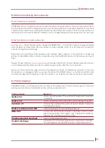
The first test section is summarised.
5. Check whether the currents expected are
achieved.
If these are too low, one or more of the battery
modules is not correctly connected to the con-
nection rail, the communication cables are fault
or incorrectly connected, the battery module has
incorrect master/slave settings or the battery
module(s) are not switched on. The maximum
voltage variation permitted is 5 V.
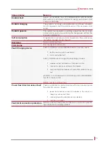
6. Confirm the input screen by clicking on “Please
confirm”.
A full load test is now performed. The system is
discharged for 5 minutes.
The following values are expected for „ Actual
current “:
SENEC.Home Li 2.5: 20 - 24 A
SENEC.Home Li 5.0: 30 - 36 A
SENEC.Home Li 7.5: 40 - 48 A
SENEC.Home Li 10.0: 45 - 65 A
7. Test the terminal connectors between the
battery modules and the connection rail for
heating up. Do this by holding the rubber
caps fitted and testing them for warming up
(may not be more than warm to the touch).
8. Confirm by clicking on “Please confirm”.


