24
1
2
3
4
5
6
7
8
9
10
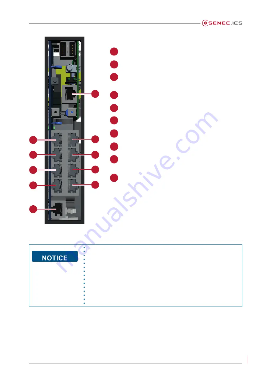
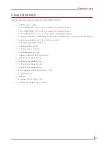
ETH (Ethernet) – connection to the customer's router
CAN 2 – future applications
PM 2 – external devices (power flow direction sensor 2/
Econamic Grid switch/etc.)
PV 2 – PV inverter
COM 2 - external devices (e.g. cascading/SENEC.Heat)
RCR/ripple control receiver
COM 1 - external devices (e.g. cascading/SENEC.Heat)
PV 1 – PV inverter
PM 1 – external devices (power flow direction sensor 1/
Econamic Grid switch/etc.)
CAN 1 – reserved for future applications
Figure 6 Overview of communication connections on the SENEC.Home Li
1
2
3
4
5
6
7
8
9
10
Note!
If necessary, terminate one cable end and thereby mark the end of a bus
system by setting a jumper on the MCU (J1 / J2 / J3 / J4). This prevents
reflections
and
signal
faults.
Example: Two devices are connected, to CAN 1 and CAN 2 respectively,
on Bus 1. Communication between the two devices is interrupted by
setting the jumper to J1. Termination with a jumper is relevant if the
data cable used is over 100 m long, poorly shielded or exposed
to strong interference sources, since these circumstances
amplify
reflections.


