


15
DO
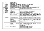
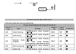
Can be programmed as impulse output terminal
of various functions as many as 13 kinds (common
port: COM). See F6.23.
OUTPUT,
output
frequency
rangeF6.32
~
F6.35, set maximum
frequency as high as 50KHz.
Analog
Input/Output
Terminal
AI1
AI1 receives voltage/current input. Jumper JP3
(for jumper terminal AI1) can select voltage or
current input mode, and voltage input is the
default one. For current input, just short the
middle and another pin with the jumper cap. AI 2
only receives voltage input. Measuring range
setting is function code F6.00
~
F6.11. (reference
ground: GND)
INPUT, input voltage range: 0
~
10V (input impedance: 100KΩ),
input current range 0
~
20mA
(input impedance: 500Ω
)
.
AI2
AO1
AO1 is able to output analog voltage/current
(total 13 kinds of signals). Jumper JP4 (for jumper
terminal AO1) can select voltage or current ouput
mode, and voltage output is the default one. For
current output, just short the middle and another
pin with the jumper cap. AO2 can only provide
analog voltage output. See F6.21, F6.22.
(Reference ground: GND)
OUTPUT, 0
~
10V DC voltage.
Output voltage of AO1, AO2 came
from PMW waveform of CPU.
Output voltage is in direct
proportion to the width of PWM
waveform.
AO2
Relay
Output
Terminal
TA1/TA2
Two-channel
programmable
relay
output
terminal, TA1/TA2, TB1/TB2, TC1/TC2 as many as
99 kinds. See F7.20.
TA-TB: normal close; TA-TC:
normal open. Contact compacity:
250VAC/2A
(COSФ=1);
250VAC/1A(COSФ=0.4),
30VDC/1A.
TB1/TB2
TC1/TC2
Power Port
+24V
24V is the common power for circuits of all digital
signal input terminals.
Maximum output current 200mA
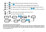
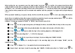
▲
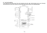
Control terminal AI1 can input both voltage and current signal, while AI2 can only input voltage signal; users can


