LED R&D Lab(VD)
61
4. Frame Installation
※ Additional correction of GAP between frame and wall (Reference)
- After the frame and wall screws are fastened, use Spacer-ETC if gap correction is needed to improve flatness.
* To check flatness, refer to the measurement method below.
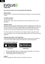
- Slightly loosen the screw on the part that needs correction. (Fig.1)
- One hand holds the frame to make space, and the other hand inserts it into the empty space using Spacer-ETC. (Fig.2)
- Tighten the screw again. (Fig.3)
(Reference) Flatness measurement method: Flatness measurement using a solid line
1. Connect the solid line to the Frame Kit Vertical bar placed on the left and right in both front and rear directions as shown below.
2. Check the flatness by checking the contact state between the frame vertical bar placed in the middle and the solid line.
Case1. When the solid line touches the front: Frame vertical bar protrudes to the front
Case2. When the solid line touches the rear: Frame Vertical bar is turned off toward the rear
※
The amount of protrusion is measured using a gap gauge.
3. Adjust the flatness using the SPACER-ETC provided as an accessory according to the flatness condition.
Case1. When the solid line touches the front side: Add Spacer-Etc around the frame vertical bar placed on the side
Case2. When the solid line touches the back: Add Spacer-Etc around the frame vertical bar
Wall
String
String
FRONT
REAR
Fig.1
Fig.2
Fig.3
IWR FRAME KIT
Summary of Contents for IFA Series
Page 1: ...LED R D Lab VD LED Display Installation Manual IWA IFA Series LH0 IWA W LH0 IFA VS Ver 3 3 ...
Page 54: ...LED R D Lab VD 53 4 Frame installation Precautions for Fastening the Screws ...
Page 130: ...LED R D Lab VD 129 8 S Box Installation and Connection S Box Grouping Support Frequency 1 2 ...
Page 131: ...LED R D Lab VD 130 8 S Box Installation and Connection S Box Grouping Support Frequency 2 2 ...
Page 200: ...Thank you ...
Page 213: ...LED R D Lab VD 212 Accessories configuration SNOW JMU Appendix 3 S BOX Accessory List ...