6 .2
Step 2. Once the AKL Relay Controller is connected (network status LED is no longer flashing),
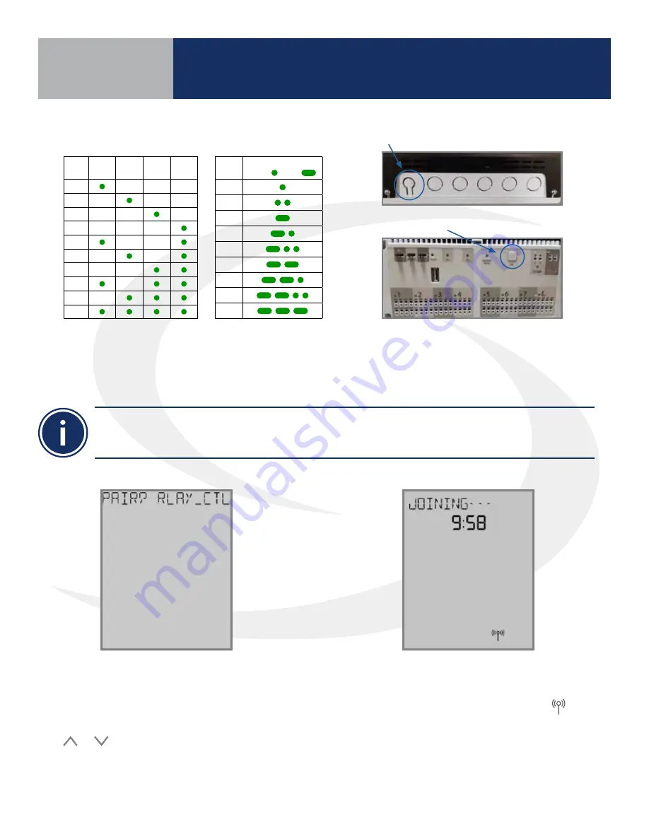
briefly press the pairing button (shown above) on the relay controller . Zone LEDs on the AKL Relay
controller will illuminate indicating the ID number of the device . This number will be used to set up
thermostats to address the correct relay controller .
ID #
Zone
1
Zone
2
Zone
3
Zone
4
1
2
3
4
5
6
7
8
9
0
AKL Relay
Controller ID
• When zone LEDs are illuminated in ID mode, the illuminated zones will be activated with an heat/cool demand
• The AKL01PRF Relay Controller uses the pulse codes shown above to identify the ID number. A short
pulse is 1 second and a long pulse is 3 seconds.
AKL01 Relay Controller ID#
Zone LED Pulse Code
ID #
LED Pattern
Short = , Long =
1
2
3
4
5
6
7
8
9
AKL01/04/06PRF Relay Controller Pairing Button
AKL08RF Relay Controller Pairing Button
The display will show JOINING- - - with a 10
minute countdown timer to show how much
time is available to join a network . The
icon will flash at the bottom of the screen
indicating that the thermostat is searching
for a network to join .
Step 3. After the AWRT10RF Thermostat
completes its boot sequence, the Relay
Controller (RLAY_CTL) will be displayed and
flashing . If another device is displayed, use the
or keys to display the correct device .
Press SELECT to start the pairing process .
Section 6
AWRT10RF Pairing without Internet
Connection (AC10RF Coordinator)
Summary of Contents for AX10RF
Page 1: ...Wireless Controls System Guide As of December 31 2018...
Page 4: ......


