4 .3
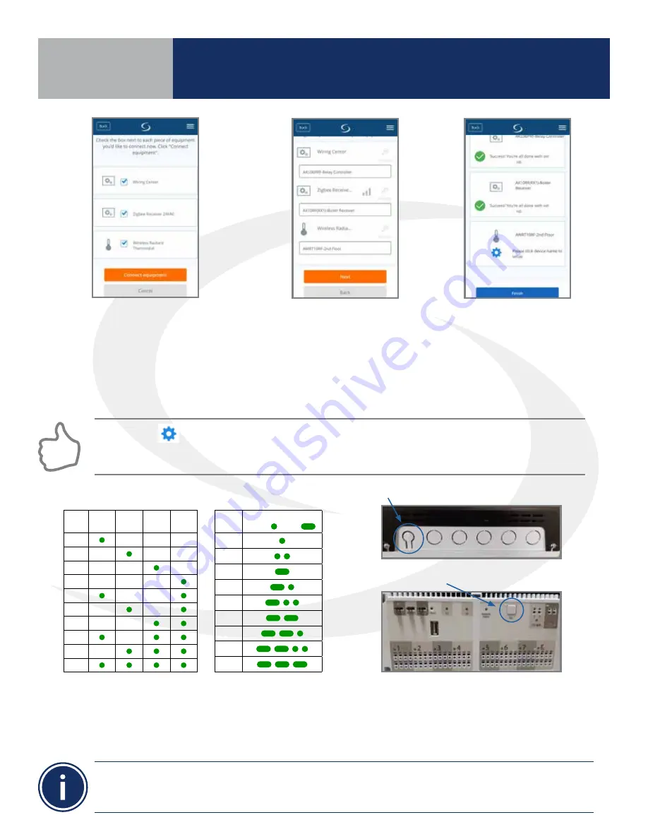
Step 7. Once the AKL Relay Controller is connected (network status LED is no longer flashing), briefly
press the pairing button (shown above) on the relay controller . Zone LEDs on the AKL Relay Controller
will illuminate indicating the ID number of the AKL device . This number will be used to set up
thermostats to address the correct relay controller .
ID #
Zone
1
Zone
2
Zone
3
Zone
4
1
2
3
4
5
6
7
8
9
0
AKL Relay
Controller ID
Step 4. Select the check boxes
for both the Wiring Center (Relay
Controller) and the Zigbee Receiver
on the Smart Home application .
Then press the orange “Connect
equipment” button .
Step 5. Give each device a
descriptive name that allows
easy identification . If there
are multiple relay controllers,
identify each with respect to
its location and/or purpose .
Step 6. Press “Finish”
to save the device
information . The
SG888ZB Gateway LED
ring will return to a
steady blue .”
Pressing the
icon on the AWRT10RF Thermostat prior to pressing Finish on the SALUS Smart Home
application starts the thermostat parameter setup. As covered in Section 8 of this manual, this can be
setup after completing the pairing process.
• When zone LEDs are illuminated in ID mode, the illuminated zones will be activated with an heat/cool demand
• The AKL01PRF Relay Controller uses the pulse codes shown above to identify the ID number. A short
pulse is 1 second and a long pulse is 3 seconds.
AKL01 Relay Controller ID#
Zone LED Pulse Code
ID #
LED Pattern
Short = , Long =
1
2
3
4
5
6
7
8
9
AKL01/04/06PRF Relay Controller Pairing Button
AKL08RF Relay Controller Pairing Button
Section 4
AWRT10RF Pairing with
Internet Connection (SG888ZB Gateway)
Summary of Contents for AX10RF
Page 1: ...Wireless Controls System Guide As of December 31 2018...
Page 4: ......


