background image

 6 .1

AWRT10RF Pairing without Internet 
Connection (AC10RF Coordinator)

Section 6

System Configuration without internet connection

Prior to using the AC10RF Coordinator on a system with no internet connection, update the 
firmware version as follows:
 

1 . Use a computer with an internet connection that meets the following requirements:


2 . Go to the SALUS Software Tools web page: 

www.salusinc.com/tools.html


3 .  Download and run the Coordinator Update Tool to update the AC10RF Coordinator by 

following the onscreen instructions .


4 . Insert the AC10RF Coordinator into a USB port on the computer when prompted to do so

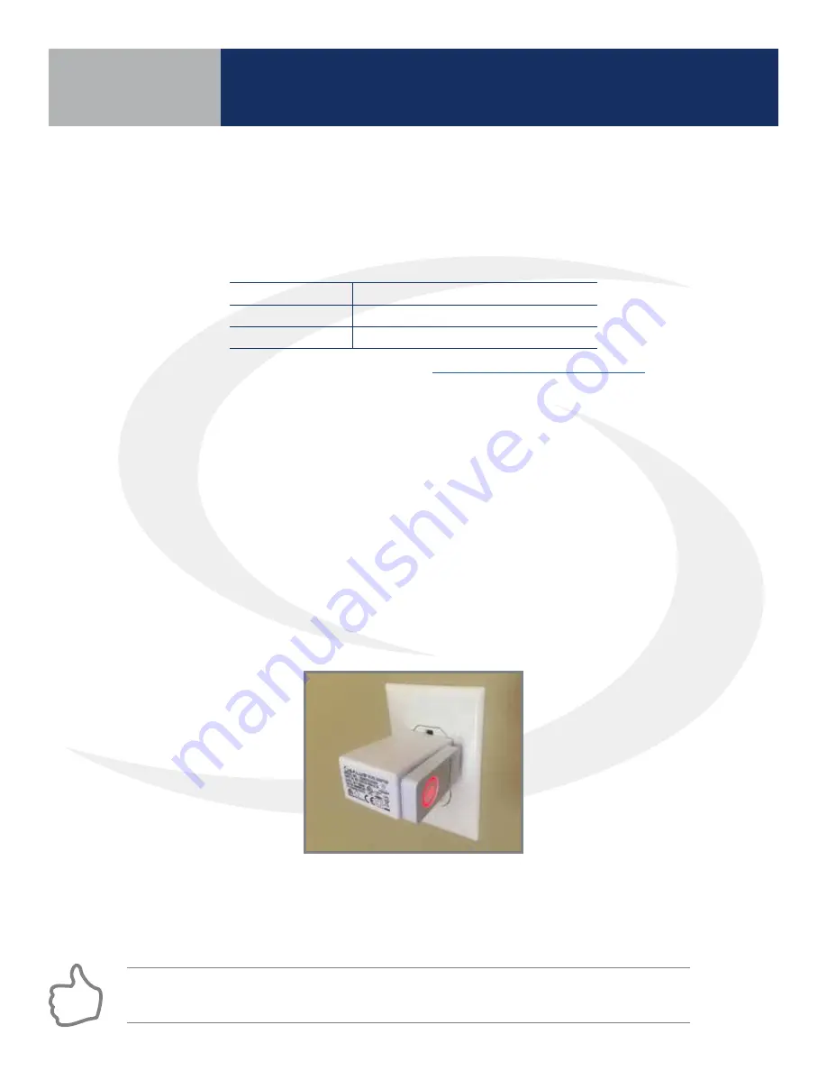
After updating the firmware, insert the AC10RF Coordinator into the provided power adapter and 
plug the two devices into an AC outlet . Verify that the LED is solid red .

Pairing with AKL01/04/06PRF and AKL08RF Relay Controllers

Before pairing, the AKL Series Relay Controller and optional AX10RF Receiver (if desired) must be 
installed and powered in accordance with installation instructions included with these devices .
 

• The Network Status LED on the AKL Relay controller should be flashing and,


•  if an AX10RF Receiver is used, the LED backlight on the Auto/Manual switch of this device 

should be flashing red .

Step 1. Press and hold the lighted red button on the AC10RF Coordinator for 5 seconds until the 
LED begins flashing, to begin pairing . When the network status LED on the AKL Wiring Center and 
the backlight on the Auto/Manual switch of the AX10RF (if used) stop flashing, they have joined the 
network and you are ready to pair the AWRT Wireless Radiant Thermostat .

COMPUTER

PC

Mac

OPERATING SYSTEM

Windows 8 or later

OSX 10.10 or later

USB PORT

Type A

Type A

If the network status LED on the AKL Wiring Center continues blinking, turn off the power to 
the device for 10 seconds.

Summary of Contents for AX10RF

Page 1: ...Wireless Controls System Guide As of December 31 2018...

Page 2: ...iver Installation 3 11 ARV10RFM Radiator Valve Actuator Installation 3 12 4 0 AWRT10RF Pairing with Internet Connection SG888ZB Gateway Pairing with AKL01 04 06PRF and AKL08RF Relay Controllers 4 1 Pa...

Page 3: ...0RF Thermostat Settings Parameters Parameter Settings Adjustments using the Display Keypad 8 1 Table AWRT10RF Wireless Radiant Thermostat Settings 8 2 Table AWRT10RF Wireless Radiant Thermostat Parame...

Page 4: ......

Page 5: ...t home products including connected thermostats a smart home hub smart plugs water valve shutoff and door and window sensors A proven leader in the European market since 2003 SALUS is currently expand...

Page 6: ...system continues to function with the settings selected AX10RF Receiver Configured for a Boiler RX1 AKL01PRF 1 Zone Pump Wiring Center AX10RF Receiver Configured for a Zone Valve RX2 AWRT10RF Wireles...

Page 7: ...d in the U S and other countries Google Play and the Google Play logo are trademarks of Google LLC As a first time user please complete a few simple steps to manage your account and equipment Let s ge...

Page 8: ...ALUS Wireless System Components without Internet Connection AX10RF Receiver Configured for a Boiler RX1 AKL01PRF 1 Zone Pump Wiring Center AX10RF Receiver Configured for a Zone Valve RX2 ARV10RFM AVA1...

Page 9: ...eway to the internet attach the ethernet cable and the power cable to the gateway only making sure it is within reach of a router or ethernet connection a For best results DO NOT CONNECT the power cab...

Page 10: ...up and attempting to establish connections Gateway is in identify mode Solid Blue Solid Green Flashing Green Solid Red Flashing Red Connected to SALUS Smart Home services Not Connected to the Internet...

Page 11: ...pe A Type A 2 Connect to the SALUS Update Tool www salusinc com tools html 3 Download and run the Update Tool by following the onscreen prompts 4 Insert the AC10RF Coordinator into a USB port on the c...

Page 12: ...wall using the provide screws and wall anchors FOR BEST RESULTS ensure that the AWRT10RFThermostat backplate is level using the integral bubble level when mounting it NOTETHE ORIENTATION ARROW molded...

Page 13: ...ce Connection Status Indicator Increment Decrement Value Confirm Selection Displays boot loader version number for 3 seconds Displays all available LCD segments for 3 seconds Displays MCU firmware and...

Page 14: ...efore wiring the device 7 Wire 120 VAC power to the L Hot N Neutral and Ground terminals labeled POWER IN 8 Wire the 120 VAC power output to the pump from L Hot N Neutral terminals labeled PUMP Connec...

Page 15: ...ired by the authority having jurisdiction In the absence of local requirements follow ANSI NFPA 70 National Electrical Code Failure to follow these requirements may lead to severe personal injury deat...

Page 16: ...operate 13 Reattach the control cover securing it with the 4 screws and switch on 120 VAC power to the unit The LED labeled POWER will be illuminated Device Installation If the priority zone is used o...

Page 17: ...ion turn 4 Unscrew two screws in the black line voltage cover and remove it 5 Disconnect the 24 VAC supply connection 6 Unscrew two screws on the left side of the control and remove the white internal...

Page 18: ...ach hole Pull gently on the wires after they are inserted to be sure they are secure Use the grooves provided in the wiring base for managing the valve wires They provide a path for wires under the wi...

Page 19: ...the cover to the desired position RX1 for system remote boiler switch RX2 for valve actuator output 6 Wire the receiver using the appropriate schematic diagram 7 Re attach the cover by engaging the c...

Page 20: ...A batteries included ensuring the correct orientation The LED on the top of the unit will flash green and then turn solid red 5 Install the actuator on the radiator valve using the RA adapter if neede...

Page 21: ...G ENv4 pdf for information about setting up the gateway Before pairing the AKL Series Relay Controller and optional AX10RF Receiver if desired must be installed and powered in accordance with installa...

Page 22: ...way s LED will flash red as it searches for devices When the components are joined to the network The Network Status Indicator on the AWRT10RF Thermostat will turn steady on T he Network Status LED on...

Page 23: ...llers identify each with respect to its location and or purpose Step 6 Press Finish to save the device information The SG888ZB Gateway LED ring will return to a steady blue Pressing the icon on the AW...

Page 24: ...ive humidity network internet status and room temperature The AWRT10RF Thermostat will enter parameter setup mode starting with parameter P 01 The current device type along with the Zigbee channel num...

Page 25: ...may take several minutes and the valve may continue to initialize after the light is no longer illuminated ARV AVA RadiatorValve Actuator Pairing Procedure Before pairing the radiator valve actuators...

Page 26: ...the screen indicating that the thermostat is searching for a network to join Step 4 Use the and keys on the AWRT10RF Thermostat to switch from RLAY_CTL to RDTR_VLV Press SELECT to initiate pairing On...

Page 27: ...timer times out or 6 valves have been paired the display will show the total number of valves paired for 3 seconds before going to the parameter setup mode In parameter setup mode the AWRT10RF Thermo...

Page 28: ...t from others in the network Press Next If the AWRT is in parameter setup mode when the Next button is pressed it will go to the Home screen Step 7 Press Finish to complete the connection to the SALUS...

Page 29: ...s shown in the installation instructions included with the device The switch on the inside cover must be configured to RX1 The LED backlight on the Auto Manual switch of the AX10RF Receiver should be...

Page 30: ...s a network the icon will stop flashing and the network channel will be displayed briefly The home screen will show PAIRING with a 10 Minute countdown timer as the AWRT10RFThermostat looks for an RX1...

Page 31: ...ostat is renamed it will immediately go to the home screen ending parameter setup Step 6 After naming the devices the application will show that set up is complete Press Finish to finalize the applica...

Page 32: ...nute countdown timer and a flashing network status indicator Step 1 On the AWRT10RF Thermostat press until PAIR RCV2 is displayed Press SELECT Step 2 Open the SALUS Smart Home mobile application and s...

Page 33: ...ute countdown timer as the AWRT10RFThermostat looks for an RX2 device After pairing is complete a confirmation screen is displayed on the AWRT10RF Thermostat for 3 seconds then the device will enter t...

Page 34: ...ostat is renamed it will immediately go to the home screen ending parameter setup Step 6 After naming the devices the application will show that set up is complete Press Finish to finalize the applica...

Page 35: ...in to Home Screen Adjust Setpoint Identify Mode Scroll Down to Edit Schedule Section 5 SALUS Smart Home Application The following illustrates the home screen of the SALUS Smart Home Application on a m...

Page 36: ...ess the Save button Schedule Setup Step 1 Scroll down on the Thermostat options menu to see default schedule Choose the edit icon at the bottom to customize the schedule Step 2 Choose from the 3 sched...

Page 37: ...desired temperature The icon indicates temporary temperature hold that will end when the next scheduled period begins Pressing Permanent Hold will display the icon shown above and will keep the setpoi...

Page 38: ...cess to the devices The setting screen will show all thermostatic radiator valves TRVs associated with the AWRT10RF Thermostat Choosing the Icon displays the list of TRVs Choosing the icon will cause...

Page 39: ...1 04 06PRF and AKL08RF Relay Controllers Before pairing the AKL Series Relay Controller and optional AX10RF Receiver if desired must be installed and powered in accordance with installation instructio...

Page 40: ...fy the ID number A short pulse is 1 second and a long pulse is 3 seconds AKL01 Relay Controller ID Zone LED Pulse Code ID LED Pattern Short Long 1 2 3 4 5 6 7 8 9 AKL01 04 06PRF Relay Controller Pairi...

Page 41: ...at will enter parameter setup mode starting with parameter P 01 The current device type along with the Zigbee channel number will be displayed Once the AWRT10RF Thermostat has joined the network SCANN...

Page 42: ...f with NO MOTOR ACTIVITY If and AX10RF Receiver is used the LED backlight on the Auto Manual switch of this device should be flashing red and the switch should be in the AUTO position Step 1 Press and...

Page 43: ...and a 10 minute timer showing how much time is left to finish pairing As each ARV AVA Valve Actuator is paired with the AWRT Thermostat the ID number displayed on the screen will increment If the user...

Page 44: ...ay shows target temperature relative humidity room temperature operation mode and network status Step 5 Press hold the flashing red pairing button on the AC10RF Coordinator for 5 seconds to complete t...

Page 45: ...in the installation instructions included with the device The switch on the inside cover must be configured to RX1 The LED backlight on the Auto Manual switch of the AX10RF Receiver should be flashing...

Page 46: ...and start normal operation The AWRT10RFThermostat display will show the current room temperature target temperature relative humidity along with indicators for the temperature mode and network status...

Page 47: ...ver is installed as shown in the installation instructions included with the device The switch on the inside cover must be configured to RX2 The LED backlight on the Auto Manual switch of the AX10RF R...

Page 48: ...hat the AX10RF Receiver is paired and connected Step 3 Press the key to exit setup and start normal operation The AWRT10RF Thermostat display will show the current date time target temperature and cur...

Page 49: ...en the SALUS Smart Home mobile application and select the drop down menu from the upper right side of the screen 2 Select Equipment All Equipment A list of connected equipment is displayed 3 Select th...

Page 50: ...the network and must be re installed as previously described Without an internet connection the SG888ZB Gateway will remain solid red Resetting the AC10RF Coordinator without Internet Connection 1 Pr...

Page 51: ...epare the thermostat for input Step 1 Press the key to enter settings menu Step 2 Use the or key to scroll to setting S 11 Step 3 Use the or key to scroll to function 86 Press SELECT Step 4 Use the or...

Page 52: ...ar the cover screw on the right side with Internet Connection To reset the AKL Wiring Centers delete them from the SALUS Smart Home mobile application as follows The AKL Wiring Center WILL NOT OPERATE...

Page 53: ...ons on the bottom surface of the unit cover The right button is for the receiver and the left is for the system with Internet Connection To reset the AX10RF Receiver delete the icon from the SALUS Sma...

Page 54: ...hree buttons on the ARV10RFM Valve Actuator for 30 seconds The light will flash amber 2 Open the battery compartment and remove one of the batteries 3 Reinsert the battery The ARV10RFM Valve Actuator...

Page 55: ...t screen and keypad Installers can access parameters on the AWRT10RF using the SALUS Smart Home application if an SG888ZB Gateway is used and connected to the internet Alternatively the parameters may...

Page 56: ...S 08 Hour 00 23 HH Format HH MM 12 11 am pm HH Format HH MM am pm S 09 Minute 00 59 MM Format HH MM or HH MM am pm S 10 Schedule WK Weekly Schedule 5 2 Weekday Weekend Schedule DAY Daily Schedule S11...

Page 57: ...ified temperature a heat demand will be signaled Off P10 Maximum Target Temperature 95 F 35 C 42 to 95 F 5 5 to 35 C Maximum allowable temperature setting for heating and cooling mode P11 Minimum Targ...

Page 58: ...lure This parameter is only available if P01 RDTR VLV P25 Key Lock Source KYS APP APP When KYS APP is selected parameter P26 Lock Setpoint can be activated from either the display and keypad of the AW...

Page 59: ...e type See Schedule OptionTable below Press SELECT Step 3 Use the and keys to change the schedule Mode if desired Press SELECT Step 4 Use the and keys to change the day or group of days for programmin...

Page 60: ...in the first period Press SELECT Step 8 Use the key to switch to the next period Set the hour minute and temperature for each period desired Step 9 Leave the time temperature fields blank to skip peri...

Page 61: ...the mode is OFF the setpoint will change to 41 F 5 C Step 2 Press SELECT to accept the new heat mode The heat mode stops flashing If the AWRT10RF Thermostat is setup as programmable the current time...

Page 62: ...he target setpoint is flashing will toggle PERMANENT HOLD which indicates the target temperature will remain as set until changed by the user While in Permanent Hold PERM DAY MM DD will be displayed a...

Page 63: ...indicates total number of valves Reset ARV AVA Actuators and AWRT10RF Thermostat Repeat pairing procedure ER LLNK RCV1 Lost Link with Receiver Configured as RX1 Reset AX10RF Receiver and AWRT10RF The...

Page 64: ...ndicates the error sequence SALUS AWRT10RF Wireless Radiant Thermostat Installation Operation Instruction Manual 47 If there is more than one error the AWRT10RF Thermostat will show the number of erro...

Page 65: ...DEMAND BOILER BOILER PUMP STAT 1 INDIRECT DHW AKL06PRF 6 ZONE WIRING CENTER 2 3 4 5 6 5 CENTRAL HEATING CH ZONES PRIMARY ZONE DHW PUMP SEE NOTE 1 THIS DOCUMENT CONTAINS INFORMATION PROPRIETARY TO AZ E...

Page 66: ...S H N R C W 24V T STAT 1 CH DEMAND DHW DEMAND BOILER BOILER PUMP STAT INDIRECT DHW AKL06PRF 6 ZONE PUMP WIRING CENTER 1 2 3 4 5 6 CENTRAL HEATING CH ZONES DHW PUMP 6 CH PUMP DHW PRIORITY SEE NOTE 1 TH...

Page 67: ...ND BOILER BOILER PUMP STAT INDIRECT DHW AKL06PRF 6 ZONE PUMP WIRING CENTER 1 2 3 6 CENTRAL HEATING CH ZONES PRIMARY SECONDARY DHW PUMP CH PUMP 4 5 6 PRIORITY ZONE SEE NOTE 1 PRIMARY PUMP THIS DOCUMENT...

Page 68: ...OILER BOILER PUMP STAT INDIRECT DHW AKL06PRF 6 ZONE PUMP WIRING CENTER 2 3 4 5 CENTRAL HEATING CH ZONES PRIMARY SECONDARY DHW PUMP CH PUMP 5 6 1 PRIORITY ZONE DHW PUMP SEE NOTE 1 PRIMARY PUMP THIS DOC...

Page 69: ...W 24V T STAT 1 CH DEMAND DHW DEMAND BOILER BOILER PUMP AKL06PRF 6 ZONE PUMP WIRING CENTER 2 3 6 CENTRAL HEATING CH ZONES PRIMARY SECONDARY DHW PUMP CH PUMP 4 1 PRIMARY PUMP NO PRIORITY SEE NOTES ZC N...

Reviews: