3 .6
Device Installation
AKL01PRF Zone Pump Wiring Center Installation
The AKL01PRF 1-Zone Pump Wiring Center pairs with an AWRT10RF Wireless Thermostat via the SG888ZB
Gateway or AC10RF Coordinator to provide a heat demand signal to the boiler and control a zone pump .
1 . Carefully read these instructions and all instructions supplied
with the unit before starting the installation .
2 . Inspect the control for damage and be sure all required parts
are included before beginning .
3 . Remove 4 screws at the corners and lift off the plastic cover .
4 . Check that the fuse installed is a 5A, slow blow fuse and that it
is inserted correctly .
5 . Attach the base of the AKL01PRF Zone Pump Wiring Center to
a wall or similar vertical structure in a suitable location near the
boiler and pumps using the hardware supplied .
The AKL01PRF Single Zone Pump Wiring Center must be installed by a qualified contractor. Installation
and repairs are to be performed according to all national and local codes required by the authority
having jurisdiction. In the absence of local requirements, follow ANSI/NFPA 70, National Electrical
Code. Failure to follow these requirements may lead to severe personal injury, death or major property
damage. DO NOT SERVICE this equipment without disconnecting the AC electrical power.
DO NOT INSTALL this control in an area where water leaks or spray are
possible. Failure to comply may result in serious injury, death or major
property damage due to electrocution or fire.
6 . BE SURE all electrical power to the device is disconnected before wiring the device .
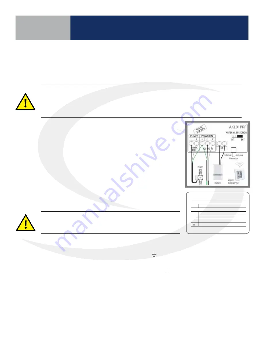
7 . Wire 120 VAC power to the L (Hot), N (Neutral) and
(Ground) terminals labeled, “POWER IN” .
8 . Wire the 120 VAC power output to the pump from L (Hot), N (Neutral) terminals labeled,
“PUMP” . Connect the ground terminal to the “POWER IN”
(Ground) terminal as shown
in the wiring schematic .
9 . Wire the output terminals labeled “XX” to the boiler thermostat input (“TT”) .
10 . Wire the thermostat contacts to R & W on the terminals labeled “24 VAC T-STAT” . If a “C” wire
is required connect it according to the drawing .
11 . Reattach the control cover securing it with the 4 screws and switch on 120 VAC power to
the unit . The LED labeled “POWER” will be illuminated .
AKL01PRF
ZigBee
Zone Pump Wiring Center
Wiring Guide
Fuse: 5A slow blow, 5x15mm (2AG)
Electrical Connections
Dry Contacts (rated 120VAC, max.2A)
XX Active Pump
120VAC Connections
L
AC Line In
Zone Pump Line Out (max. 1/6 HP)
N
AC Neutral
Earth Ground
Issue Date: May 2017
For PDF Installation guide go to
www.salusinc.com
Technical Helpline 1-855-557-2587
Warning
•
This product must be installed by qualified personnel and the installation must comply with the codes and regulations applicable to the
municipality where this product is installed. Failure to do so could lead to injury, death, or prosecution.
•
Always disconnect the AC power before installing or working on AC power components.
LED Indicators
Name Color Meaning
Power
120 VAC power ON
Zone 1
Zone pump active
Network
Status
Searching for
network
Paired to a network
Zone Pump
The zone pump will be activated when
the thermostat calls for heat.
Auxiliary Output
XX: Contact closure when zone pump is ON.
Factory Default
To restore the wiring center to Factory Default,
press and hold the Pair button until the
Network Status LED turns off (~10 secs).
Note: Restoring to Factory Default will remove
the wiring center from the network and delete
all associated devices.
WCID#
Zone LED Pattern:
short=1, long=3
1
2
3
4
5
6
7
8
9
Operational Summary
Wiring Center ID Number
Section 3
Summary of Contents for AX10RF
Page 1: ...Wireless Controls System Guide As of December 31 2018...
Page 4: ......


