3-1-44
2A3/4
3-1-8 Installing the dehumidifier heaters (service part)
Dehumidifier heater installation requires the following parts:
Two dehumidifier heaters (P/N 33960020): for 220 - 240 V specifications
Two dehumidifier heaters (P/N 34860030): for 120 V specifications
Two heater bases (P/N 54107410)
Eight BVM4 x 06 bronze binding screws (P/N B1304060)
Eight EDS-2 edgings (P/N M2104210)
Relay wire (P/N 53310390)
Six SG-110 V0 bands (P/N M2107200)
<Procedure>
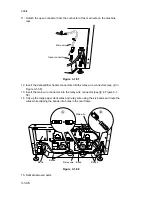
1. Fit the dehumidifier heaters to the heater bases using two screws for each.
Screws
Screws
Dehumidifier heater
Left
Dehumidifier heater
Heater base
Heater base
Right
Figure 3-1-53
2. Remove the two screws from each of the deck right cover, deck left cover and deck
rear cover and then the covers.
3. Open the large paper deck.
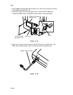
4. Detach the deck paper conveying motor connector.
5. Remove the spring from the deck paper conveying motor bracket.
6. Remove the four screws holding the deck paper conveying motor bracket and then
the bracket.
7. Remove the two screws holding the deck paper conveying unit assembly and then
the assembly.
Connector
Spring
Screws
Screws
Deck paper conveying
motor bracket
Deck paper conveying
unit assembly
Figure 3-1-54
Summary of Contents for Ri 4230
Page 3: ...SERVICE MANUAL Ri 4230 5230 ...
Page 13: ...4230 5230 S M MCA THEORY AND CONSTRUCTION SECTION I I Theory and Construction Section ...
Page 14: ...1 1 5 2A3 4 CONTENTS 1 1 Specifications 1 1 1 Specifications 1 1 1 ...
Page 100: ...4230 5230 S M MCA ELECTRICAL SECTION II II Electrical Section ...
Page 119: ......
Page 138: ......
Page 159: ...4230 5230 S M MCA III Set Up and Adjustment Section III SET UP AND ADJUSTMENT SECTION ...
Page 448: ...2A3 4 3 6 3 25 Toner scatters at the leading edge of the image See page 3 6 17 ...


