2A3/4
1-3-28
CN5-B10
CN2
CN1-4
CN2-B9
CN2-B11
CN2-A6
CN2-A7
CN2-A8
CN2-B3
CN2-A10
CN2-A5
EPCB
TRM
TFM
TFM–
TFM+
TRM–
TRM+
TLDS
TLS
TNS SIG
TNS CONT
DB REM
TNS
HVTPCB
DB
CN5-B8
CN1-6
DB CONT
CN5-B1
CN1-13
24 V DC
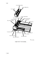
Figure 1-3-26
Developing section block diagram
Toner density is detected by the toner sensor (TNS).
The sensor section of the toner sensor detects the ratio of toner to carrier in the
developer near it and converts it into a voltage. As more toner is used, the ratio of toner
to carrier decreases, increasing the toner sensor output voltage.
When the ratio drops below the specified value, the increase in toner sensor output
voltage triggers toner replenishing. When toner is added and the ratio of toner to carrier
returns to normal, the toner sensor output voltage drops to the point where toner
replenishing stops.
Summary of Contents for Ri 4230
Page 3: ...SERVICE MANUAL Ri 4230 5230 ...
Page 13: ...4230 5230 S M MCA THEORY AND CONSTRUCTION SECTION I I Theory and Construction Section ...
Page 14: ...1 1 5 2A3 4 CONTENTS 1 1 Specifications 1 1 1 Specifications 1 1 1 ...
Page 100: ...4230 5230 S M MCA ELECTRICAL SECTION II II Electrical Section ...
Page 119: ......
Page 138: ......
Page 159: ...4230 5230 S M MCA III Set Up and Adjustment Section III SET UP AND ADJUSTMENT SECTION ...
Page 448: ...2A3 4 3 6 3 25 Toner scatters at the leading edge of the image See page 3 6 17 ...


