


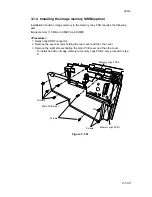

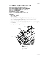


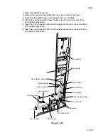


3-1-43
2A3/4
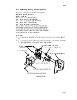
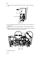
7. Pass the 4-pin connector of the key counter through the apertures in the key
counter cover retainer and middle right cover, and insert into the 4-pin connector
inside the machine.
8. Seat the projection of the key counter cover retainer in the aperture in the middle
right cover, and fasten them both to the machine using the two screws.
9. Refit the screw to the machine front side of the middle right cover.
10. Fit the key counter cover with the key counter assembly inserted to the key counter
cover retainer on the machine.
Screw
4-pin connector
4-pin connector
Aperture
Middle right cover
Key counter cover retainer
(66060021)
M4
×
10 screw
(B4304100)
Key counter cover
M4
×
10 screw
(B4304100)
M4
×
6 screw
(B4104060)
Figure 3-1-52
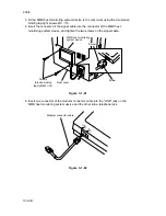
11. Insert the key counter into the key counter assembly.
12. Turn the main switch on and enter the maintenance mode.
13. Run maintenance item U204 and select “KEY COUNTER.”
14. Exit the maintenance mode.
15. Check that the message requesting the key counter to be inserted is displayed
when the key counter is pulled out.
16. Check that the counter counts up as copies are made.
Summary of Contents for Ri 4230
Page 3: ...SERVICE MANUAL Ri 4230 5230 ...
Page 13: ...4230 5230 S M MCA THEORY AND CONSTRUCTION SECTION I I Theory and Construction Section ...
Page 14: ...1 1 5 2A3 4 CONTENTS 1 1 Specifications 1 1 1 Specifications 1 1 1 ...
Page 100: ...4230 5230 S M MCA ELECTRICAL SECTION II II Electrical Section ...
Page 119: ......
Page 138: ......
Page 159: ...4230 5230 S M MCA III Set Up and Adjustment Section III SET UP AND ADJUSTMENT SECTION ...
Page 448: ...2A3 4 3 6 3 25 Toner scatters at the leading edge of the image See page 3 6 17 ...