


2A3/4
2-3-16
( 1 ) Paper deck motor drive circuits
IC8.4Y
+5 V DC
A
B
12
11
CPU
IC7
58
1
R4
2
13
IC8.3Y
IC6.4
R36
PDMPCB
A
B
10
8 1
B
2
C
3
1
2
E
GROUND
AGROUND
CN1-8
CN7-1
CN7-2
9
8
9
2
C
1
E
3
B
+5 V DC
1
R24
2
+24 V DC
1
R25
Q3
Q1
Q5
2
1
D1
SIG
D4
2
K
A
+24 V
DC
PDM1
2
C
1
E
3
B
1
K
2
A
+5 V DC
UPSW1
14
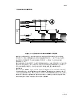
Figure 2-3-12 Paper deck motor 1 drive circuit
The following is a description of the paper deck motor 1 drive circuit. Paper deck motors
1 and 2 are identical.
When pin 14 of the CPU IC7 goes low, transistor Q1 is turned on causing paper deck
motor 1 (PDM1) to rotate. When transistor Q1 is turned off, paper deck motor 1 (PDM1)
stops. A brake circuit ensures the prompt stopping of the motor. When transistor Q1
turns off, transistor Q3 turns on, supplying 24 V DC to CN7-1 thereby preventing paper
deck motor 1 (PDM1) from rotating further under momentum.
When the right cassette lift is raised past the limit, upper limit switch 1 (UPSW1) turns
on, taking the level at pin 58 of the CPU IC7 low, which turns transistor Q1 and hence
paper deck motor 1 (PDM1) off. This level change is also passed to pin 9 of a protective
circuit consisting of IC8.3, forcing paper deck motor 1 (PDM1) off directly in case the
CPU IC7 fails.
Summary of Contents for Ri 4230
Page 3: ...SERVICE MANUAL Ri 4230 5230 ...
Page 13: ...4230 5230 S M MCA THEORY AND CONSTRUCTION SECTION I I Theory and Construction Section ...
Page 14: ...1 1 5 2A3 4 CONTENTS 1 1 Specifications 1 1 1 Specifications 1 1 1 ...
Page 100: ...4230 5230 S M MCA ELECTRICAL SECTION II II Electrical Section ...
Page 119: ......
Page 138: ......
Page 159: ...4230 5230 S M MCA III Set Up and Adjustment Section III SET UP AND ADJUSTMENT SECTION ...
Page 448: ...2A3 4 3 6 3 25 Toner scatters at the leading edge of the image See page 3 6 17 ...