3-1-48
2A3/4
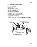
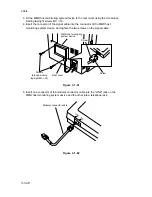
3. Fit the MMD host monitoring system device to the rear cover using the two bronze
binding tap-tight screws M3
×
16.
4. Insert the connector of the signal cable into the connector of the MMD host
monitoring system device, and tighten the two screws on the signal cable.
Screws
(bronze binding
tap-tight M3
×
16)
Screw
Screw
Rear cover
MMD host monitoring
system device
Figure 3-1-61
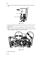
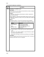
5. Insert one connector of the modular connector cable into the "LINE" jack on the
MMD host monitoring system device and the other into a telephone jack.
LINE
TEL
Modular connector cable
Figure 3-1-62
Summary of Contents for Ri 4230
Page 3: ...SERVICE MANUAL Ri 4230 5230 ...
Page 13: ...4230 5230 S M MCA THEORY AND CONSTRUCTION SECTION I I Theory and Construction Section ...
Page 14: ...1 1 5 2A3 4 CONTENTS 1 1 Specifications 1 1 1 Specifications 1 1 1 ...
Page 100: ...4230 5230 S M MCA ELECTRICAL SECTION II II Electrical Section ...
Page 119: ......
Page 138: ......
Page 159: ...4230 5230 S M MCA III Set Up and Adjustment Section III SET UP AND ADJUSTMENT SECTION ...
Page 448: ...2A3 4 3 6 3 25 Toner scatters at the leading edge of the image See page 3 6 17 ...


