background image

2011© Ropam Elektronik s.c.  

[email protected]


www.ropam.com.pl

   Installation and operating manual: NEO/NEO-PS v.1.4S EN

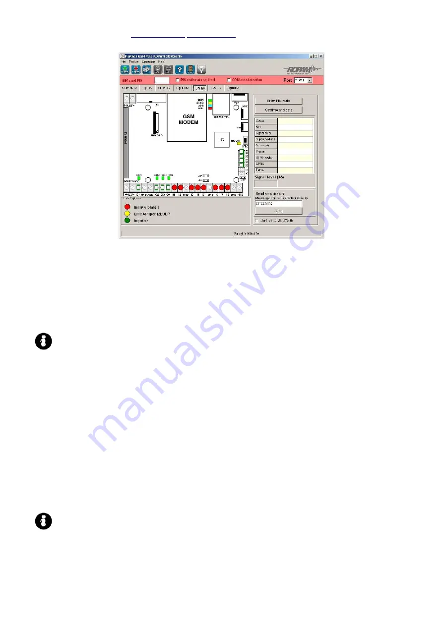
6.6.1 MONITORING OF INPUT STATES

The input states are displayed on round indicators mounted in places of screws securing module 

connectors. The state of each input is signaled by the color of the indicator:

RED – input violated

GREEN – input not violated
YELLOW- input tampered (sabotaged)

BURGUNDY- input blocked (SMS/TP)

Remarks:         

ON-LINE monitoring requires an active connection via RS232TTL or modem 

connection

in the ON-LINE mode the module does not perform its standard functions e.g. it does  

not send SMS messages when inputs violated etc.

6.6.2 MONITORING OF OUTPUT STATES

The activation of module outputs is possible by using this option. An initial test of the signaling device 

without starting the alarm procedure is possible. To trigger a given output (in accordance with the polarity set 

in the OUTPUTS bookmark), the white indicator mounted in the place of screws securing the module connector 
(physically in the place of the connector associated with the module output), should be marked by clicking the 

mouse button on it. After clicking on it, the  

„√ ”

 character signifying the input activation will be displayed. A 

second click will mark the indicator and switch the activation off.

6.6.3 ENTER PIN CODE

Pressing ENTER PIN CODE, will cause that a PIN code which is currently displayed in the SIM CARD PIN 

CODE field entering command is sent to the module telephone.

Testing modules containing SIM cards which belong to different operators, without the necessity of 
configuration changing and it’s recording, is possible by using this option. The configuration entered in the 

MGSM module, must have marked the option PIN CODE NOT REQUIRED, to prevent automatic PIN code 
insertion by the module procedure.  

REMARKS:        

all procedures involved in replacing the SIM card, like jumper selection, interface and  

module connections, should be performed after disconnecting the module power supply  
and ensuring  all available anti-static protection safeguards

6.6.4 SET TIME AND DATE

Pressing the SET TIME AND DATE FIELD, transfers the time and date form the PC computer to the 

module. The correct time and date is required for transmission test sending in accordance with the clock and for 
proper event recoding in the event memory. 

28

Summary of Contents for MGSM 4.0+

Page 1: ...NEO NEO PS Alarm control panels with GSM communication controlled by the TPR 1 TouchPanels GSM notifiaction and control module GSM communicatiom module Installation manual 2011 Ropam Elektronik ...

Page 2: ...s of EU directive no 91 157 EEC and 93 86 EEC 2 WARNINGS For safety reasons the equipment may be installed only by qualified personnel Prior to installation read the instructions All installation procedures should be performed with the power supply disconnected The power supply should not be switched on when the external antenna is disconnected operating the equipment with the antenna disconnected...

Page 3: ...peration with TSR 1 sensor digital temperature sensor sending information after exceeding L or H value SMS instantaneous value in SMS thermostat function controlled with OUT5 and OUT6 outputs inputs 8 120 wide range of reactions e g arm disarm delayed counter choice of operating configuration 2EOL NC 2EOL NO EOL NC NO I1 I6 outputs I7 I8 NC NO triggered or additional two alarm inputs in each TPR 1...

Page 4: ...a fully functional alarm system While using two panels we reactive system with 20 inputs 10 outputs one area with night mode and one with installed GSM communication and operation What is more NEO NEO PS central enables creating simple automation applications with remote control via SMS CLIP Flexible functions enables using them in systems in which is applied control of binary signals temperature ...

Page 5: ...ding or dial in programming mode communication with the computer LOG BLUE LED signaling network signal level FAIL RED LED signaling failure firmware update in programming mode INCOM YELLOW LED signaling SMS receiving or incoming dial AC DC GREEN LED signaling power supplies main or backup DC PR connection initiation programming via RS232 TTL switch MODEM GSM industrial telephone FME F FME F antenn...

Page 6: ... the module the availability and distance of alarm signal sources and trigger signals e g the control panel the availability of power supplies or installation possibility of such in vicinity the MGSM 4 0 10V 14V 1A min buffered 13 8V DC power supplies recommended e g recommended dedicated PSR or PSR RF the MGSM 4 0 PS 17V 20V 30VA the 17V 20V AC terminals are used for connection the secondary wind...

Page 7: ...O NEO PS module has a VSR socket intended for connecting the VSR 2 VSR 1 and the AMR 1 audio or other e g utilized in CCTV voice synthesizer modules provisioned for listening in on the object The voice synthesizer can record and relay a voice command when an event alarm occurs in the system Replay is performed automatically after establishing voice communication The message is repeated cyclically ...

Page 8: ... NC normally closed NO normally open alarm outputs relay RELAY zero potential contacts open collector OC BELL negative power supply controlled high current positive power supply controlled 12V TYPE POLARITY INPUTS NC NO EOL 2EOL NC 2EOL NO I1 I6 I7 I8 GND or 12V GND or 12V X X X Ix input operates with a given type of polarity X Ix input does not operate with a given type of polarity Polarity type ...

Page 9: ...nly I7 I8 configuration NO trigger by 12V the jumper JI7 or JI8 isn t installed Polarity type only I7 I8 NC trigger by 12V the jumper JI7 or JI8 isn t installed 4 4 DEVICE CONNECTION TO OUTPUTS The NEO NEO PS module has got outputs for control and signaling the operation status O1 O2 in the active state we can connect NO or disconnect NC 12V power supply transistor output controlling the power sup...

Page 10: ...stical and or optical signaling Output O1 O2 connecting a load 12VDC Output O1 o2 connecting a relay 12VDC O3 O8 in the active state can connect NO or disconnect NC the 0V power supply GND the open collector OC transistor outputs control the ground of the power supply 100mA max Output O3 O8 connecting a siren 12VDC 100mA max acoustical and or optical signaling 10 ...

Page 11: ...The PARTNER GSM software is intended for operation on PC class computers running under the WINDOWS 9X Me 2000 XP VISTA operating system Communication between PARTNER GSM and NEO is accomplished via the RS232 port or the USB 1 1 2 0 port utilizing communication cables with a built in RS 232 RS232 TTL or a USB RS232 TTL converter Dedicated RS232 MGSM or USB MGSM cables are recommended 5 1 SOFTWARE D...

Page 12: ...odules HELP HELP open help file HOME PAGE open page www ropam eu READ open file with configuration from computer HDD CD etc rpm file WRITE write current configuration to computer HDD local OPEN CLOSE COM PORT RS 232 port marked in the COM bookmark COM CLOSED not active COM OPEN active RTY aktywny READ F4 read module configuration communication active communication active red color communication no...

Page 13: ...ld become visible Furthermore the functioning communication is signalized by the flashing light next to the port number and the COMMUNICATION ESTABLISHED message is displayed in the PARTNER GSM software footnote together with the device type modem and module firmware version number 9 Configure the module perform ON LINE tests etc During the read write etc this is signalled with an appropriate mess...

Page 14: ...M cable install VCP drivers from CD or downloaded from ww ropam com pl or download from the manufacturer http www ftdichip com Drivers VCP htm 6 FUNCTIONAL DESCRIPTION Functions descriptions and configuration method are explained in the windows and with messages in the PARTNER GSM software REMARK The constantly updated software and newly implemented new functions can be downloaded by using the PAR...

Page 15: ...he international format Remarks The SMS CENTER is the SMS center number of the module SIM card telephone GSM operator When number is wrong or missing SMS sending will be blocked In case of entry lack PARTNET GSM SMS center does not saves configuration in the module it is advised to center e g 48 6 2 3 OBJECT TELEPHONE NUMBER This is the number of the SIM card in the module telephone This field is ...

Page 16: ...F I7 I8 NO NC trigger by GND 0V VDC or lub plus VDC according to JI7 JI8 settings NO denotes the GND level triggered signal 0V DC NORMALLY OPEN state input The I7 I8 inputs can be triggered by GND 0V DC or plus VDC depending on the JI7 and JI8 settings The input in the NORMALLY OPEN state is triggered by the GND 0V signal The input in the NORMALLY OPEN state is triggered by the plus U signal JI7 i...

Page 17: ...tor JI7 is by default ON EOL in the software I7 in PARAMETRICAL state triggered by disconnecting parametric resistor 2 2 kΏ JI7 is OFF EOL in the software UNACCEPTABLE JI8 is by default ON EOL in the software I8 in PARAMETRICAL state triggered by disconnecting parametric resistor 2 2 kΏ JI8 is OFF EOL in the software UNACCEPTABLE 2EOL NO denotes an input in the configuration two parametric NORMALL...

Page 18: ...o be displayed directly on the telephone screen flash or whether it should be read from the received mail box Selecting the option configures the input SMS type for the violation and entry restore REMARKS it should be remembered that FLASH type SMS messages can be very easily overlooked because they are not recorded in the telephone they disappear from the telephone screen when there is an incomin...

Page 19: ...rmed mode as a switch violation of the entry activates the armed mode and the entry returns to its normal status armed mode is deactivated Marking the option CANCEL NOTIFICATION results in terminating the SMS and VOICE messages when the armed mode alarm is switched off regardless of the progress of the acknowledgment action LINE TAMPER The SMS message content relating to the sabotaging of 2EOL NO ...

Page 20: ...to configure module outputs Output control can be performed via SMS messages CLIP short telephone connections so called ring events in the system e g ALARM logical functions AND OR NOR XOR The module main board contains the following one high current input O1 electronically protected against overload three low current OC outputs O2 O8 6 4 1 OUTPUTS OPTIONS POLARITY Choice of configuration in norma...

Page 21: ...hone numbers fields in the Numbers authorized to control CLIP panel or by entering any number In addition the module reaction to incoming calls can be defined by using the Incoming calls option ALARM output is active when alarm is triggered def normal input ARMED output active indicator armed when module counter has finished countdown time to exit When this option is active the settings in the TIM...

Page 22: ...UT OUTPUT VIOLATION option selected The module enables controlling a given output by using the selected inputs outputs and one of four logical functions logical function and AND AB Y where Y output A B input output It is a logic circuit which has the following functions Signal value 1 is present at the output only if both input signals have the logical value 1 A B Y 0 0 0 0 1 0 1 0 0 1 1 1 logical...

Page 23: ...ation times costs time duration of connections input delays CLIP waiting for SMS message sending access codes to chosen security code protected functions reactions to incoming calls temperature measurement options thermostat timers 6 5 1 TRANSMISSION TEST Option enables determination of a testing method of the module connection with the GSM network To activate the options mark TRANSMISSION TEST RE...

Page 24: ...d in the bookmark REMARKS the maximum number of characters 20 do not enter national characters the module can be tested via an SMS message by sending the module access code if the code is identical to the one in the module memory it will reply by sending a test SMS e g test on demand xxxx where xxxx access code e g Adam example adam reply GSM module OK 6 5 2 FAILURES The module permanently monitor...

Page 25: ...nection Time is measured from the moment of call received detection Set the number of seconds in the range 1 64 ENTRY TIME s determines the maximum entry time counted from the moment of DELAYED type input entry violation Set the number of seconds in the range 1 600 EXIT TIME s determines the maximum standby switch on time delay NORMAL type of inputs after ARM DISARM input violation Set the number ...

Page 26: ... entered in Celsius C within 55 C to 125 C variation 1 C SMS CONTENT SMS content shall be entered in the bookmark and it is sent after event occurrence reaching determined value Maximal SMS length is 20 characters Do not use special characters e g Polish letters CALL marking the option triggers calling voice notification after particular event detection VSR this column enables configuring the cont...

Page 27: ...ization at 5 C and another when the temperature exceeds 10 C and falls below 5 C once again REMARKS high temperature has to be higher than the low temperature H L measurement frequency 60s 6 5 7 TIMERS Options allow time and timer functions configuration ON OFF enter timer switching on and off time gg mm ss ACTION activation action shall be chosen for a particular TIMER switched off timer deactiva...

Page 28: ...d with the module output should be marked by clicking the mouse button on it After clicking on it the character signifying the input activation will be displayed A second click will mark the indicator and switch the activation off 6 6 3 ENTER PIN CODE Pressing ENTER PIN CODE will cause that a PIN code which is currently displayed in the SIM CARD PIN CODE field entering command is sent to the modul...

Page 29: ...d be used Before installation and choice of GSM operator it is recommended to perform a network signal level measurement by using a standard cell phone and placing the phone for ca 5 minutes in the expected installation place and observing the network level indicator Attention should be paid to the stability of the reading and potential influence of weather and time of the year e g a forested area...

Page 30: ...ware can be downloaded manually from www ropam com pl and installed in the same place as the previous software version 6 7 2 UPDATING THE NEO SOFTWARE FIRMWARE When replacing the software firmware version 1 Load the file containing a new firmware version This can be performed in two ways a Pressing the IMPORT FILE LIST field in the Internet connection mode will cause downloading the current flash ...

Page 31: ...cator Successfully terminated operation will be signalized with the message FLASH TERMINATED SUCCESFULLY PRESS THE PR SWITCH TO RESUME COMMUNICATION Remarks If the WRITE SOFTWARE TO MODULE switch is not active set the appropriate COM in the bookmark and open the port using the switch which will change it s state to As the procedure starts the following message may be displayed Error BOOT LOADER DI...

Page 32: ...2011 Ropam Elektronik s c sales ropam com pl www ropam com pl Installation and operating manual NEO NEO PS v 1 4S EN EVENT DATE AND TIME EVENT ADDITIONAL INFO 32 ...

Page 33: ...h network level signal OK registered in network registered in network problem in sending 3 SMS messages consecutively setting parity sum error OUT1 output overload OUT1 output OK failed dial no connection with telephone restore of telephone connection power supply restart internal restart e g WATCHDOG modem restart SMS sending failed PIN failure 24H line alarm INFO line alarm COUNTER line alarm al...

Page 34: ...on OR notification is activated in case of occurring at least one event 6 9 2 SEND MMS TO The tap allows defining message receivers TELEPHONE NUMBER maximum 8 telephone numbers can be defined from the tap NUMBERS E MAIL ADDRESS maximum 4 addresses of electronic mail can be defined MMS HEADING video camera description e g garden etc which is sent with MMS message REMARKS charge for MMS messages is ...

Page 35: ... equal to 100kB MMS COUNTER the option allows setting the limit of sent MMS messages The counter is cleared after 24h factory preset 10 MMS BLOCK the option allows setting block time for sending another MMS messages from a particular input in minutes The option allows limiting costs for example in case of launching VIDEO detection as a source of notification triggering MODULE STATUS the tap enable...

Page 36: ... power supply with built in two channel radio controller range 50 m 150 m two channel with relay outputs extended operation modes configuration and output status registered in the EEPROM memory the configuration status is restored to the status before the power supply failure which assures real device control e g alarm system controlled with an input status digital transmission control of MGSM 4 0...

Page 37: ...field 3 inncorect password output TAMPER entering three wrong codes triggers output tamper type counting is separate for every TP panel Disconnected output TAMPER losing connection communication of the central triggers tamper type output TP tamper enabled active option triggers antisabotage protection for a particular TP panel Backlight the entry delay active option causes total illuminati on of p...

Page 38: ...rt codes deletes users codes and set the master code 5555 Save settings pressing the button causes saving the settings only in touch panels Read settings pressing the button causes reading the settings only from touch panels 7 REMOTE CONFIGURATION OF THE MODULE THROUGH SMS MESSAGES The functionality of the module enables a remote alteration of selected configuration parameters It is effected throu...

Page 39: ... INPUTS The configuration SMS syntax has the following format yyyy Ix parameter1 parameter2 parameter3 Where yyyy access code Ix input with the no x 1 8 Parameter Description Example Remarks NO NC EOL 2EOLNC 2EOLNO OFF Input polarization see paragraph 6 3 1 NC INFO 24H INSTANT ARM DISARM DELAYED COUNTING INTERIOR DEL Input type see paragraph 6 3 1 INFO TIME tttt Input sensitivity TIME 1500 tttt ti...

Page 40: ...ATION FAILURE NO AC SUPPLY SABOTAGE ACTIV 110000000100 0 x 1 option active x 0 option inactive Marking a few options results in output activation according to the selected logical function the logical function OR factory settings SMSON aaaa The content of the SMS message which activates a particular output SMSZAL pump on aaaa maximum 20 characters SMSOFF aaaa The content of the SMS message which d...

Page 41: ...SMS messages with failure information FAILURE 10 xx a number between 1 and 20 SMSATTEMPTS xx The counter determines the number of attempts for sending a SMS message corresponding to a particular problem with transmission for example temporary lack of GSM range SMSATTEMPTS 10 xx a number between 1 and 20 ex yyyy COUNTER SMS 40 FAILURE 10 SMSATTEMPTS 3 yyyy access code 7 6 Remote configuration of TI...

Page 42: ...ssion test clock 1111 RESETTEST yyyy RESTART Restarting of modem and module 1111 RESTART yyyy DOWNLOADING x Remote activation deactivation of the modem connection function 1111 DOWNLOADING 1 X 1 function enabled x 0 function disabled 8 MODULE OPERATION SATUS SIGNALING The NEO module is equipped with an optical status signaling system Four LED diodes mounted on the module board display the operatio...

Page 43: ...to send 3 consecutive SMS messages 4 low power supply voltage U 11V on the power supply input 5 overloaded O1 high current output I 1A 6 no communication with the module telephone 7 PIN code error 8 SIM card error SIM card has been not detected by the module 9 no communication with PSR PSR RF module 10 no communication with FGR 4 module 11 GRPR connecting error message transmission MMS E MAIL 12 A...

Page 44: ...uring blocking its functions remain unchanged 1234 LOCK 10000000 The I1 input will be blocked yyyy UNLOCK All blocked inputs are unblocked UNLOCK 1234 All inputs are unblocked 9 3 Remote control of output status NEO It is done by CLIP or SMS messages Output parameters are configured in the OUTPUTS tab CLIP control consists in carrying out the connection with a telephone number Depending on the con...

Page 45: ... O3 O4 0 no potential O1 output open O2 O3 O4 System Armed Disarmed Status armed disarmed Network P Network level status P 1 5 Failure No failure Failure status Clock not set Date and time missing status No AC supply For the version with integrated PS feeder BAT discharged For the version with integrated PS feeder No connection with PSR Loss of PSR connection status PSR status AC no AC hi DC1 low ...

Page 46: ...RN tab Violation SMS VIOLATION tab Tamper Tamper content REMARKS Outputs without defined content are ignored Tampers refers only to 2EOL NC and 2EOL NO inputs 9 7 FGR 4 module status check downloading pictures Sending SMS command in a form yyyy PICTURE x x x x causes module response in a form of MMS where yyyy is an access code x VIDEO input number 1 2 3 4 Command yyyy access code Response Example...

Page 47: ...ccess code Response Example yyyy DOWNLOAD yy_mm_dd name jpg MMS with read picture 1111 DOWNLOAD 09_09_10 00142315 jpg 9 9 USSD codes recharging a PRE PID SIM card via scratch card code Command yyyy access code Response Example yyyy loadprepaid xxxx SMS from network with reply USSD code for the correct recharging of the SIM card account or problem with sending a USSD code for errors in account rech...

Page 48: ...Failure counter The number of SMS sending attempts Dial round count 40 10 3 1 TIMES Call time Entry time Exit time 20s 20s 30s Transmission test not set 11 TECHNICAL DATA TECHNICAL PARAMETERS Value Power supply NEO NEO PS U 9V 14V DC min max 1 3A min recommended use PSR or PSR RF U 16V 20V AC min max 30VA min U 20V 28V DC min max 0 7A min Output voltage of the NEO PS Un 13 8V DC 2 U 10 0V 13 8V DC...

Page 49: ...0 1800 1900 MHz automatically switched Transmission type SMS VOICE GPRS FGR 4 AUDIO IN OUT 2Vrms Module input type programmable NO NC EOL 2EOL NC 2EOL NO Line resistance for a given type no violation violation hi Z 30Ω 30Ω hi Z hi Z 2k2 1k1 2k2 2k2 1k1 AI analog inputs Uin 0 10V DC max Z 30K Resolution 10mV accuracy 1 of full range Communication system EIA 485 system bus RS323TTL connection to the...

Page 50: ...am com pl www ropam com pl Installation and operating manual NEO NEO PS v 1 4S EN 50 NEO NEO PS Alarm control panels with GSM communication controlled by the TPR 1 Touch Panel GSM notifiaction and control module GSM communicatiom module ...

Reviews: