4-28
16
15
1
2
3
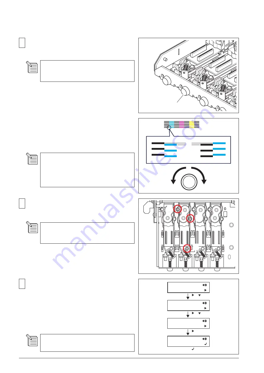
When the lines other than K are above the K lines, turn
the Adjustment Screw CW.
When the lines other than K are below the K lines, turn
the Adjustment Screw CCW.
Adjust the head positions referring to the left-
end K head as the base position. The position
of K head on the left end does not need to be
adjusted.
Tighten the screws fixing the head in order as shown in
the figure, using the Torque Driver (ST-056).
Torque for tightening is
2kgf • cm (20cNm)
.
Make sure not to tighten the screws too strong.
Print the test pattern again.
If the result is not satisfactory, repeat step 11 to 15.
If the VERTICAL test print reult is satisfactory, select
[HEAD ADJUST]> [BIAS]> [TEST PRINT], and print the
BIAS test pattern again.
If the BIAS test print result is not satisfactory, repeat
BIAS ADJUSTMENT.
The shifting of lines should be smaller than 1/2
dot.
14
Turn the Adjustment Screw to make the lines of each color
in the test pattern straight.
ADJUSTMENT SCREW
[ ]
PRINT MENU
HEAD ADJUST
HEAD ADJUST
BIAS
BIAS
TEST PRINT
[ ]
[ ]
SERVICE MENU
PRINT MENU
[ ] [ ]
[ ]
Position of the printing moves 1 line by turning
the screw 1/6 turn.


