P1
P2
P3
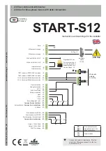
ON
11
10
9
8
DIP
12 13 14 15 16 17 18 19 20 21 22 23
28 29 30
24 25 26 27
FR1
FR2
MF3
MF2
MF1
FUSE 2
1.6 A
FUSE 1
10 A
LED
WARNING
FUSE 3
200 mA
START-S12
Technical manual
-5-
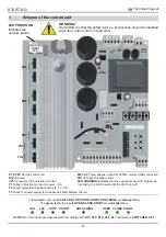
LSO LSC STOP PHOTO UNFOLDING OPEN CLOSE START
The
red led
in the input
LSO-LSC-STOP-PHOTO-UNFOLDING EDGE
are
always lit on
The
green led
in the inputs
OPEN-CLOSE-START
are
normally lit on
P1 P2 P3
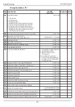
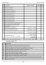
Set the control unit
DIP
not used
JP1
Connector for temperature sensor
F1
Fuses protection motor and power:
10A
F2
Fused protection terminal boards (4, 5):
1.6A
F3
Fuses for power supply for accessories and safeties:
200mA
MF1-2-3
Three-phases output for 230Vac motors delta connection
FR1-2
Output for brake motor
LED WARNING
Indicates that the capacitors are still charged, be-
fore taking the central wait until the LED turns off.
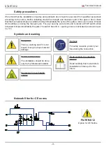
WARNING!
We remind you that the safety devices, accessories should be installed
when the control unit is not powered.
1
Scheme of the control unit
WARNING: If the inputs are desactivated from display with
S13
,
S14
,
S15
,
S16
,
S17
red leds are
SWITCHED OFF
LED POWER ON
Indicates the
network power
1 2 3
4 5
6 7
Summary of Contents for START-S12-M
Page 30: ...START S12 Manuale tecnico 30 10 Note ...
Page 63: ...START S12 M Technical manual 30 10 Note ...
Page 95: ...START S12 Technical manual 30 10 Note ...
Page 128: ...START S12 Instrución 31 10 Note ...
Page 129: ...START S12 Instrución 32 ...
Page 130: ...START S12 Instrución 33 ...
Page 164: ...START S12 Notice d emploi 31 10 Note ...
Page 165: ...START S12 Notice d emploi 32 ...
Page 166: ...START S12 Notice d emploi 33 ...

