background image

EB TECHNOLOGY  S.r.l.


Corso Sempione 172/5, 


21052 Busto Arsizio VA Italia 
tel. +39 0331.683310
fax.+39 0331.684423 
 
[email protected]   
www.ebtechnology.it

NOLOGO S.r.l.


via Cesare Cantù 26, 


20020 Villa Cortese MI Italia 
tel. +39 0331.430457 
fax.+39 0331.432496 
 
[email protected]   
www.nologo.info

Summary of Contents for START-S12-M

Page 1: ...rt COSTA di sicurezza Comune Servizi e Sicurezze Calza Antenna Comune Servizi e Sicurezze Antenna 23 Switch di rallentamento in APRE Pedonale Ingresso comando bussola 26 25 24 27 Switch di rallentamento in CHIUDE Comune Servizi e Sicurezze 30 28 Uscita 12Vdc 60mA FOTO A in chiusura 29 Uscita 12Vdc 60mA Collegare questo punto al morsetto n 8 per avere il test sulle fotocellule Altrimenti collegarlo...

Page 2: ...t corrente continua NC normalmente chiuso NA o NO normalmente aperto Contatto pulito isolato dalle tensioni di alimentazione Par Descrizione Pag 1 Schema della centrale Schema cablaggio 6 1 1 Descrizione collegamenti elettrici 7 2 Utilizzo e funzioni del pannello di controllo 8 2 1 Visualizzazione stato centrale 2 2 Accesso alle impostazioni e selezione dei parametri 2 3 Esempio di utilizzo Menù e...

Page 3: ...allati solo da personale tecnico qualificato nel pieno rispetto delle norme di legge Prima di iniziare l installazione verificare la robustezza e la consistenza meccanica del cancello o portone verificare che gli arresti meccanici siano adatti a fermare il movimento del cancello o portone anche nel caso di un guasto ai finecorsa elettrici o durante la manovra manuale Per una maggiore sicurezza è consi...

Page 4: ...compatibilità del manuale tecnico All accensione della centrale il display visualizza un numero a 4 cifre Tale numero corrisponde alla versione del software installato nel microprocessore della centrale Vi consigliamo di verificare se il numero visualiz zato corrisponde a quello presente sulla copertina del manuale tecnico come mostrato in figura 1518 CODICEVISUALIZZATO Vers fi rmware 1518 Verificare ...

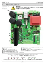
Page 5: ... di protezione motori e potenza 10A F2 Fusibile di protezione morsetti 4 5 1 6A F3 Fusibile alimentazione accessori e sicurezze 200mA MF1 2 3 Uscita trifase per motore trifase 230 Vac a triangolo FR1 2 Uscita per bobina freno motore LED WARNING Indica che i condensatori sono ancora ca richi prima di prendere la centrale attendere che il led si spenga ATTENZIONE Si ricorda che l installazione della...

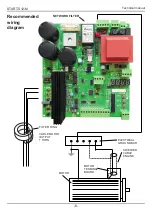
Page 6: ...BARRA DI TERRA FILTRO RF AD ANELLO CAVO USCITA MOTORE 1 GIRO MOTORE MORSETTIERA MOTORE CAVO SCHERMATO MOTORE START S12 Manuale tecnico 6 Schema cablaggio consigliato FILTRO di RETE ...

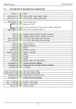
Page 7: ...Vac 11 Uscita 12 14 Vac 800mA per accessori FCA 12 Ingresso Fine Corsa Apre FCC 13 Ingresso Fine Corsa Chiude Stop 14 Ingresso STOP Foto A 15 Fotocellula attiva solo in chiusura Sicurezza 16 Ingresso ANTI IMPACCHETTAMENTO Apre 17 Ingresso APRE Chiude 18 Ingresso CHIUDE Start 19 Ingresso comando START Costa 20 COSTA di sicurezza contatto NC 8K2 Comune 21 Comune Servizi e Sicurezze Comune 22 Calza A...

Page 8: ... P3 La START S12 è dotata di un display che ne permette una programmazione semplice ed intuitiva La struttu ra del menù è stata attentamente studiata in modo da permettere una più chiara e immediata impostazione dei tempi di lavoro e delle logiche di funzionamento Si ricorda che è possibile accedere alle impostazioni solo ad automazione chiusa 2 Utilizzo e funzioni del pannello di controllo t23c P...

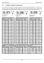
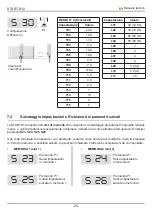
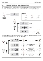
Page 9: ...l Cap 4 r 09 Visualizza TENSIONE attuale sui condensatori Mostra TEMPERATURA dissipatore IGBT VALORE RESISTIVO su ingresso COSTA CONTATORE MANOVRE espresso in decine Il pto indica le migliaia P1 Accedere al menù t P2 L r P1 conferma 1 pressione 2 pressione 3 pressione Premere e rilasciare Tenere premuto Rilasciare SIMBOLI UTILIZZATI Confermando con il tasto P1 sull impostazione R accediamo alle im...

Page 10: ...1 Accedere al menù t P2 2 volte S P1 conferma S 01 S 32 P2 Confermando con il tasto P1 viene abilitato l accesso alle impostazione del gruppo S ora aiutandosi con il pulsante P2 portarsi sulla funzione S 32 poi confermare con P1 P1 OK S 33 DISATTIVAZIONE PASSWORD P1 OK Selezionando la funzione S33 verrà rimosso il codice di prote zione Attendere 10 secondi come da display per redendere effettiva l...

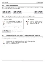
Page 11: ...o dieci secondi se viene premuto il pulsante P1 verrà annullata l operazione Il contatore delle manovre mostra fino a 999 999 aperture Il Display mostra le prime 4 cifre più si gnificative 344 2 Se si visualizza ad esempo il numero qui pro posto vorrà dire che l automazione ha effettua to più di 344 200 manovre ESCLUDERE CICLO DI FUNZIONAMEN TO INTERROTTO ALLO SPEGNIMENTO Tenere premuto P1 all accen...

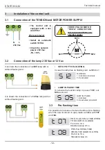
Page 12: ...ult IMPOSTAZIONE LAMPEGGIO S12 Nel caso venga installato un lampeggiante senza scheda di intermittenza occorre settare a 1 l im postazione S12 INTERMITTENZA 1 Attivata Default 0 Disattivata LAMPEGGIANTE IN PAUSA 3 2 Collegamento del LAMPEGGIANTE 230 Vac oppure 12 Vac Collegamento alla rete elettrica 230 Vac Viene riportato il collegamento del lampeggiante 12 Vac con o senza scheda di intermittenza...

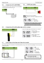
Page 13: ... Abilità ingresso COSTA 0 Disattivato Default 1 Attivato Contatto COSTA 0 Contatto NC 1 Contatto 8K2 Default S 38 Nel caso venga installata un costa di sicurezza collegare il contatto ai morsetti 20 21 3 6 Collegamento COSTA di sicurezza Contatto NC o 8K2 12 13 14 15 16 17 18 19 20 21 22 23 Nella figura viene mostrato il collegamento di entrambe i finecorsa ma su questa centrale si possono utilizzar...

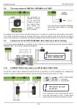
Page 14: ... TX RX IRPA 1 SENSOR 3DD Tramite i morsetti 28 29 30 è possibile collegare le fotocellule a filo come il nostro modello IRPA1 SEN SOR 3DD In figura ne viene mostrata una tipica installazione 30 28 Uscita 12Vdc 60mA FOTO A in chiusura 29 Uscita 12Vdc 60mA Nel caso la centrale venga utilizzata su porte a impacchettamento rapido è possibile installare delle fotocel lule per anti impacchettamento Nel ca...

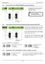
Page 15: ...presenti altri ingressisotto TEST S 09 Abilità TEST su ingresso FOTO 1 Attivato 0 Disattivato S 06 Abilità TEST su ingresso INGRESSI SICUREZZA 1 Attivato 0 Disattivato 3 13 Inibizione Fotocellula A in fase di chiusura S 03 Inibizione Foto A in ch 1 Attivata 0 Disattivata L impostazione S03 viene utilizzata per abilitare l ini bizione dell ingresso FOTOA quando interviene il fine corsa di rallentame...

Page 16: ... Default 0 Disattivato S 21 Ingresso SWITCH in CHIUDE 1 Attivato Default 0 Disattivato Per il collegamento del FRENO si consiglia fare attenzione alla polarità Impostare poi la funzione S19 a seconda del freno installato S 19 POLARITA USCITA FRENO 0 freno disattivato con tensione Deafult 1 freno attivato con tensione 3 15 Collegamento del FRENO MECCANICO e FRENO interno S 37 E possibile attivare i...

Page 17: ... l accelerazione impostata Attiva l APERTURA con velocità di rallentamento Attiva la CHIUSURA con velocità di rallentamento P1 Accedere al menù t P2 L r P1 conferma P2 1 press P2 2 press P2 3 press Premere e rilasciare Tenere premuto Rilasciare SIMBOLI UTILIZZATI P2 Confermando con il tasto P1 sull impostazione R accediamo al sotto funzioni prima scegliendole con i pulsanti P2 e P3 e poi conferman...

Page 18: ...ui comandi APRE e CHIUDE funzione UOMO PRESENTE 8 Passo Passo con richiusura alla pausa Uomo Presente Come funzione S01 4 in aggiunta sui comandi APRE e CHIUDE funzione UOMO PRESENTE S 02 1 Richiusura alla riaccensione Default 0 Esegue ciclo completo di apertura pausa e chiusura SOLO se nell istante in cui è mancata tensione di alimen tazione l automazione si trovava in posizione di aperto S 04 1 ...

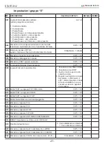
Page 19: ...e in apre step da 0 1 s 2 0 T 04 Impostazione posizione di inizio decellerazione in chiude step da 0 1 s 1 0 T 11 Impostazione posizione di inizio inibizione lettura ingresso fotocellula Non viene considerato se S03 1 step da 0 1 s 0 5 T 12 Tempo di inibizione lettura ingresso COSTA mors 16 dalla partenza dal FINE CORSA APRE Questa impostazione è utile quando tale ingresso è utilizzato per l anti ...

Page 20: ...URA da 1 a 200 40 L 05 Accelerazione in APERTURA da 1 a 99 8 L 06 Accelerazione in CHIUSURA da 1 a 99 8 L 07 Decelerazione in APERTURA da 0 a 25 8 L 08 Decelerazione in CHIUSURA da 0 a 25 8 L 09 Assorbimento massimo del motore per considerare automazione in STOP in Ampere 5 0 L 10 Assorbimento massimo del motore per considerare anomalia in Ampere 7 0 L 11 Potenza sull uscita FRENO da 1 a 70 50 Ven...

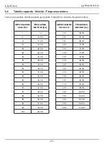
Page 21: ...14 50 10 17 00 15 19 50 20 22 00 25 24 50 30 27 00 35 29 50 40 32 00 45 34 50 50 37 00 55 39 50 60 42 00 65 44 50 70 47 50 75 49 50 80 52 00 85 54 50 90 57 00 95 59 50 100 62 00 IMPOSTAZIONE VELOCITA FREQUENZA MOTORE Hz 105 64 50 110 67 00 115 69 50 120 72 00 125 74 50 130 77 00 135 79 50 140 82 00 145 84 50 150 87 00 155 89 50 160 92 00 165 94 50 170 97 00 175 99 50 180 102 00 185 104 50 190 107 ...

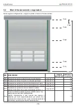
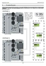
Page 22: ... 28 29 30 24 25 26 27 FR1 FR2 MF3 MF2 MF1 FUSE 2 1 6 A FUSE 1 10 A LED WARNING FUSE 3 200 mA 1 2 3 4 5 6 7 P1 P2 P3 DIP 12 13 14 15 16 17 18 19 20 21 22 23 28 29 30 24 25 26 27 FR1 FR2 MF3 MF2 MF1 FUSE 2 1 6 A FUSE 1 10 A LED WARNING FUSE 3 200 mA 1 2 3 4 5 6 7 S 35 Funzione BUSSOLA 1 Attivata 0 Disattivata CENTRALE A CENTRALE B Durante il funzio namento quando l altra porta è in ma novra viene vi...

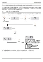
Page 23: ...ta la perdita di tutti i valori impostati 7 1 Ripristino parametri default Analizzando le schede riassuntive dei parametri Cap 10 è possibile visualizzare i valori di deault che verran no caricati durante questa operazione di RESET Selezionare il parametro S18 come riportato P1 Accedere al menù t P2 2 volte S P1 conferma S 01 S 18 P2 P1 OK Per annullare l operazione ripremere il tasto P1 entro 10 ...

Page 24: ... 5 T12 0 0 T13 0 1 T14 0 1 T15 0 0 T16 0 0 DEFAULT 2 Porte h3 5m Impostazione Valore T01 3 5 T02 2 5 T03 2 0 T04 1 0 T05 3 0 T06 3 0 T07 0 0 T08 0 0 T09 0 0 T10 4 5 T11 0 5 T12 0 0 T13 0 1 T14 0 1 T15 0 0 T16 0 0 DEFAULT 3 Porte h2 5m Impostazione Valore T01 2 5 T02 2 0 T03 1 0 T04 0 5 T05 3 0 T06 3 0 T07 0 0 T08 0 0 T09 0 0 T10 3 5 T11 0 5 T12 0 0 T13 0 1 T14 0 1 T15 0 0 T16 0 0 DEFAULT 1 2 3 que...

Page 25: ...di poi richiamare 2 differenti configurazioni da voi impostate MEMORIA 1 slot 1 MEMORIA 2 slot 2 S 23 S 24 S 25 S 26 Premendo P1 Salva impostazioni in memoria 1 Premendo P1 Salva impostazioni in memoria 2 Premendo P1 Carica impostazioni salvate in memoria 1 Premendo P1 Carica impostazioni salvate in memoria 1 DEFAULT 4 Scorrevoli Impostazione Valore T01 20 0 T02 10 0 T03 17 0 T04 3 0 T05 10 0 T06 1...

Page 26: ...ilizzato per l anti impacchettamento per evitare che lo srotolamento iniziale del telo copra momentaneamente la fotocellula e quindi faccia riaprire l automazione step da 0 5 s 1 0 T 13 Tempo di inibizione controllo consumo motore alla partenza step da 0 1 s da 0 a 2 s 0 2 T 14 Tempo di pausa nelle inversioni di marcia step da 0 1 s da 0 a 2 s 0 1 T 15 Tempo di ritardo arresto motore dopo rilevame...

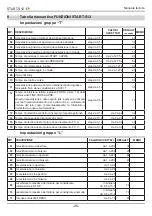
Page 27: ...metrica 1 Considera come FINECORSA 2 Considera come STOP 3 Inverte il motore per 2 s alla velocità minima 4 Regola in automatico la coppia del motore in riferimento a L09 valore impostato in base al motore installato non per cancelli scorrevoli o apparati di sicurezza 2 S 09 Abilita TEST su ingresso FOTOCELLULA 0 Off 1 On 0 S 10 Abilita TEST su ingresso COSTA 0 Off 1 On 0 S 11 Abilita TEST su ingr...

Page 28: ...ETTAMENTO mors 16 0 disattivato 1 attivato 0 S 37 Freno elettronico interno si attiva per 2s dopo l arresto del motore 1 decelerazione leggera 4 decelerazione pesante 5 non accelera ne frena 6 frenata leggera 9 frenata pesante 0 S 38 Contatto COSTA di sicurezza mors 20 21 0 contatto N C 1 contatto 8K2 1 IMP DESCRIZIONE R 01 Attiva apertura fino al rilascio di P1 con accelerazione impostata R 02 Att...

Page 29: ...nsiglia di controllare la tensione di rete E stata superata la soglia di overcur rent impostata nella funzione L 10 Se neccessario aumentare tale valore Sui condensatori è presente una tensione troppo bassa Si consiglia di controllare la tensione di rete Codice di protezione errato Provare a rinserire il codice Attendere che cali la temperatura sul dissipatore La centrale nota un consumo supe rior...

Page 30: ...START S12 Manuale tecnico 30 10 Note ...

Page 31: ...tive alla compatibilità elettromagnetica Riferimento alle norme armonizzate EN61000 6 2 2006 EN 61000 6 3 2007 A1 2011 EN 13241 1 2003 A1 Par 4 3 5 IL PRODOTTO E CONFORME ai requisiti essenziali richiesti dall articolo 3 dalla seguente direttiva comunitaria per l uso al quale i prodotti sono destinati 1999 5 CE DIRETTIVA 1999 5 CE DEL PARLAMENTO EUROPEO E DEL CONSIGLIO del 9 marzo 1999 riguardante...

Page 32: ...o Arsizio Va Italia Cette déclaration est présentée sous la seule responsabilié du constructeur et si applica ble de son représentant autorisé Italia 03 07 2014 Administrateur KONFORMITÄTSZERTIFIKAT Der Unterzeichner bescheinigt dass das Produkt START S12 allen technischen Produktegesetzen laut den Europäische Gesetzen 2006 42 CE 2006 95 CE 2004 108 CE e 99 5 CEE entspricht Alle Radiofrequenzprüfu...

Page 33: ...21052 Busto Arsizio VA Italia tel 39 0331 683310 fax 39 0331 684423 posta ebtechnology it www ebtechnology it NOLOGO S r l via Cesare Cantù 26 20020 Villa Cortese MI Italia tel 39 0331 430457 fax 39 0331 432496 info nologo info www nologo info ...

Page 34: ...ommon Services Safeties Antenna Socks Common Services Safeties Antenna 23 Slow down switch OPEN Partial opening Interlock input 26 25 24 27 Slow down switch ClOSE Common Services Safeties 30 28 Output 12Vdc 60mA PhOTO A closing 29 Output 12Vdc 60mA 230 Vac Connect this point to terminal no 8 for the photo test Otherwise connect it to the ter minal board no 10 mF1 mF2 mF3 Three phase output for thr...

Page 35: ... NA o NO normally open Isolated contact isolated from power supply Par Desricption Pag 1 Scheme of the control unit wiring diagram 6 1 1 Description of the electrical connections 7 2 Use and functions of the control panel 8 2 1 State of the control unit 2 2 Settings and parameters 2 3 Example how to use the MENU and information 9 2 4 Set up a password for programming 10 2 5 Cancel of the operation...

Page 36: ...e gate or door check that the mechanical stops are suitable to stop immediatelly the cycle of the gate or door even in case of faulty limit switches or during the manual cycle For your security we recommend to install a STOP switch when activated it stops immediatelly the gate The switch has a N C opening in case is activated as shown in par no 3 7 Safety precautions Damage For safety reasons prot...

Page 37: ...tilation systems Rapid doors Sliding automation Check the software version and compatibility with the operating manual When the control unit is turn on you can see 4 numbers in the display This is the software number We suggest to check this number with the version on the manual see pic 1602 CODE Vers fi rmware 1602 Check that the number on the display correspond to the firmware on the operating ma...

Page 38: ...ction motor and power 10A F2 fused protection terminal boards 4 5 1 6A F3 fuses for power supply for accessories and safeties 200mA mF1 2 3 Three phases output for 230Vac motors delta connection FR1 2 Output for brake motor LED WARNINg Indicates that the capacitors are still charged be fore taking the central wait until the LED turns off WARNINg We remind you that the safety devices accessories sh...

Page 39: ...ElECTRICAl gROUND BAR fIlTER RINg CABlE MOTOR OUTPUT 1 TURN MOTOR MOTOR TERMINAl BOARD ShIElDED CABlE ENgINE START S12 M Technical manual 6 Recommended wiring diagram NETWORK FILTER ...

Page 40: ...0 12 14 Vac output 800mA for accessories Out 12 Vac 11 12 14 Vac output 800mA for accessories LSO 12 Open limit switch LSC 13 Closing limit switch Stop 14 STOP Photo A 15 Photo A closing Safety edge 16 Safety or unfolding Open 17 OPEN Close 18 CLOSE Start 19 START Costa 20 SAFETY edge NC 8k2 contact Common 21 Common Services Safeties Common 22 Antenna Socks Common Services Safeties Antenna 23 Ante...

Page 41: ...To go back to the previous group press P2 and P3 P2 P3 START S12 M has a display for a simple and fast programming The menu has been designed for a clear and fast set up of the working time and the logic of the control unit You can set up the control unit only when the door is closed 2 Use and functions of the control panel t23c P Fcc In this case the door is with closing limit switch and that the...

Page 42: ... capacitors Show temperature of the IgBT Show the resistive value in the Safety edge input terminal board no 20 Show the cycle counters point indicated the thousands P1 Access to the MENU t P2 L r P1 confirm 1st Press 2nd Press 3rd Press Press and release Keep pressed Release SYmBOlS In the function R if you press P1 you can choose the group function first select P2 and P3 and then confirm with P1...

Page 43: ...1 Access to the menu t P2 2nd press S P1 confirm S 01 S 32 P2 In the function S if you press P1 you can choose the group function first select P2 now you can go to the function S32 and then confirm with P1 P1 OK S 33 DEACTIVATION OF ThE PASSWORD P1 OK If you select the fucntion no S33 you can cancel the password Wait 10 seconds to confi rm the operation finished entering the 4 digit Press P1 to co...

Page 44: ...el the operation If you press P1 in 10 seconds this operation will be cancelled The counter counts up to 999 999 openings The display shows the first 4 most significant digits 344 2 If you read these number it means that the installation has made 344200 cycles DESACTIVATE THE COMPLETE CYCLE Of ThE CYCLE fUNCTION WhEN ThE TENSION hAS BEEN INTERRUPTED keep pressed P1 when turns on P1 2 7 Desactivati...

Page 45: ...05 lAMP IN PAUSE 1 Activated 0 Deactivated standard SET UP OF ThE LIghTINg S12 In case the lamp has no flashing card set S12 in 1 flAShINg 1 Activated standard 0 Deactivated LAmP IN PAUSE TImE 3 2 Connection of the lamp 230 Vac or 12 Vac N L 230 Vac LAmP 12 Vac LAmP 230 Vac It is shown the connection of a 12 Vac lamp with or without flashing card 3 3 Pre flashing time It is possible to increase or ...

Page 46: ...16 17 18 19 20 21 22 23 20 21 22 23 S 22 SAFETY EDGE 1 Activated Standard 0 Deactivated SAFETY EDGE contact 0 NC contact 1 8K2 contact Standard S 38 Connect the safety edge at terminal board no 20 and 21 3 6 Connection of the 8k2 safety edge or N C contact 12 13 14 15 16 17 18 19 20 21 22 23 The picture shows the connection of both limit switches but you can connect it separately You can use only ...

Page 47: ...7 TX RX IRPA 1 SENSOR 3DD The terminal boards 28 29 30 are available for the connection of the photo beams with cable like IRPA 1 SENSOR 3DD You can see a standard installation 30 28 Output 12Vdc 60mA PHOTO A when closing 29 Output 12Vdc 60mA In case the control units is installed in rapid rise doors is possible to connect photobeam for unfolding the curtain In case the intervention of safeties th...

Page 48: ... if are inputs are not in test S 09 TEST in PHOTO OUTPUT 1 Activated 0 Deactivated S 06 TEST in the INPUT safeties 1 Activated 0 Deactivated 3 13 Deactivation of the PHOTOCELL A when the gate is closing S 03 Photocell A deactivated 1 Activated 0 Deactivated If you set S03 it deactivates the PHOTO A after in tervention of slow down LS If S03 is 1 the time of function T11 is not considered 12 13 14 ...

Page 49: ...put when CLOSING 1 Activated Standard 0 Deactivated Pay attention when you connect the brake and pay attention of the polarity Program with S19 according to the type of brake S 19 POLARITY OUTPUT OF THE BRAKE 0 brake deactivate with tension Standard 1 brake activate with tension 3 15 Connection of the brake FR1 FR2 and internal brake S 37 You can activate the INTERNAL BRAKE S37 activating this fun...

Page 50: ...n CLOSINg with slow down P1 Access to the functions t P2 L r P1 confirm P2 1st press P2 2nd press P2 3td press Press and release Keep pressed Release SYmBOlS P2 In the function R if you press P1 you can choose the subfunction group fun ction first select P2 and P3 and then confirm with P1 Now you can go to the function R01 R02 R03 r 01 r 02 r 04 P3 P1 P1 P1 P1 P1 S r 05 r 06 Activate the LIghT ACT...

Page 51: ... Dead man function Same as function S01 3 OPEN and CLOSE with Dead man function function 8 Bistable function with automatic reclosing after pause time Dead man function Same as function S01 4 OPEN and CLOSE with Dead man function function S 02 1 Reclosing when turning on Standard value 0 Complete open and close ONLY when the tension has been interrupted when the gate is open S 04 1 It detects the ...

Page 52: ...start position of OPEN decelerating time value from 0 1 s 2 0 T 04 Set up START position of the CLOSING deceleration time value from 0 1 s 1 0 T 11 Set up start position of deactivation of the photocelle It is not considered if S03 is set in 1 value from 0 1 s 0 5 T 12 Deactivation Time of the input SAFETY EDGE term S16 from starting of LSO This function is useful in case of anti folding to avoid ...

Page 53: ...L 04 Maximum speed CLOSING from 1 to 200 40 L 05 OPENING acceleration from 1 to 99 8 L 06 CLOSING acceleration from 1 to 99 8 L 07 OPENING deceleration from 0 to 25 8 L 08 CLOSING deceleration from 0 to 25 8 L 09 Motor absorption in case of STOP Ampere 5 0 L 10 Motor absorption in case of problems Ampere 7 0 L 11 Power in the BRAKE OUTPUT from 1 to 70 50 Are now given the parameters that allow you...

Page 54: ...17 00 15 19 50 20 22 00 25 24 50 30 27 00 35 29 50 40 32 00 45 34 50 50 37 00 55 39 50 60 42 00 65 44 50 70 47 50 75 49 50 80 52 00 85 54 50 90 57 00 95 59 50 100 62 00 Speed setting FREQUENCY Hz 105 64 50 110 67 00 115 69 50 120 72 00 125 74 50 130 77 00 135 79 50 140 82 00 145 84 50 150 87 00 155 89 50 160 92 00 165 94 50 170 97 00 175 99 50 180 102 00 185 104 50 190 107 00 195 109 50 200 112 00...

Page 55: ...ction S35 and connect the 2 control units 6 INTERLOCK Function S 35 INTERLOCK fUNCTION 1 Activated 0 Deactivated CONTROL BOARD A CONTROL BOARD B When one con trol uniti is wor king you can see in the di splay FBUSS and it cannot ac cept other com mands CONTROl BOARD A CONTROl BOARD B CONTROl BOARD B 24 25 26 27 24 25 26 27 8 9 10 11 8 9 10 11 CONTROl BOARD A ...

Page 56: ...5 m and sliding gates WARNINg This operation cancel all settings 7 1 Restore factory settings Checking those paramenter of the parameters Chapter no 8 yuo can look the set up during the RESET of the control unit Select the paragraph S18 as shown P1 Access to the functions t P2 2nd press S P1 confirm S 01 S 18 P2 P1 OK Wait 10 seconds otherwise if you press P1 in 10 seconds this operation will be c...

Page 57: ...eed doors h3 5m Set up Val T01 3 5 T02 2 5 T03 2 0 T04 1 0 T05 3 0 T06 3 0 T07 0 0 T08 0 0 T09 0 0 T10 4 5 T11 0 5 T12 0 0 T13 0 1 T14 0 1 T15 0 0 T16 0 0 T17 12 STANDARD 3 High speed doors h2 5m Set up Val T01 2 5 T02 2 0 T03 1 0 T04 0 5 T05 3 0 T06 3 0 T07 0 0 T08 0 0 T09 0 0 T10 3 5 T11 0 5 T12 0 0 T13 0 1 T14 0 1 T15 0 0 T16 0 0 T17 12 STANDARD 1 2 3 These parameters are the same for all 3 set...

Page 58: ...ferents set up MEMORY 1 slot 1 MEMORY 2 slot 2 S 23 S 24 S 25 S 26 Press P1 Save all set up MEMORY 1 Press P1 Save all set up MEMORY 2 Press P1 Charge set up of MEMORY 1 Press P1 Charge set up of MEMORY 2 STANDARD 4 sliding gates Set up Val T01 20 0 T02 10 0 T03 17 0 T04 3 0 T05 10 0 T06 10 0 T07 2 0 T08 2 0 T09 120 0 T10 5 0 T11 0 0 T12 0 0 T13 1 T14 10 T15 0 T16 0 Set up Val L01 30 19 Hz L02 30 ...

Page 59: ...tion of the motor when the gate is opening or closing step from 0 1 s from 0 to 2 s 0 2 T 14 Pause time of reverse of the direction of the motor step from 0 1 s from 0 to 2 s 0 1 T 15 STOP of the motor after detecting the LSO step from 0 1 s from 0 to 3 s 0 s T 16 Time of delay of the motor when detecting the LSC step from 0 1 s from 0 to 3 s 0 s T 17 Lead time on the release of the brake before s...

Page 60: ...sidered as limit switch 2 Considered as STOP 3 Reverse motor of 2 sec at min speed 4 According to the set up of function L09 and according to the motor not for sliding gates of safety devices 2 S 09 Activate the TEST in the input PHOTOCELL 0 Off 1 On 0 S 10 Activate the Test in the SAFETY EDGE input 0 Off 1 On 0 S 11 Activate the TEST in the input STOP 0 Off 1 On 0 S 12 Activate the flashing in th...

Page 61: ...2 seconds after motor stopping 1 light acceleration 4 heavy acceleration 5 neither acceleration nor braking 6 light braking 9 heavy braking 0 S 38 Safety edge contact terminal board no 20 21 0 N C contact 1 8K2 contact 1 SET UP DESCRIPTION R 01 Activate Opening until P1 has been released with acceleration set up R 02 Activate CLOSING until P1 has been released with acceleration set up R 03 Activat...

Page 62: ...ension of 240 Vac in the capacitors Check the network tension The overcurrent level of programm L10 has been exceeded If necessary incre ase the value The tension in the capacitors is too low Check the network tension Code not correct Try a new code Wait until the temperature in the spendthrift is reduced The control unit has an absorption of more than 1 5A even if the motor is not working Check t...

Page 63: ...START S12 M Technical manual 30 10 Note ...

Page 64: ...ES with what is outlined in the European Community directives 2006 95 CE EEC DIRECTIVE 2006 95 ISSUED BY THE EUROPEAN COUNCIL on December 12 2006 harmonizing the legislation of the member countries regarding electric materials for use within certain voltage limits Reference to harmonized standards EN 60335 1 2004 108 CE EEC DIRECTIVE 2004 108 CE ISSUED BY THE EUROPEAN COUNCIL on December 15 2004 h...

Page 65: ...sto Arsizio Va Italia Cette déclaration est présentée sous la seule responsabilié du constructeur et si applica ble de son représentant autorisé Italia 01 02 2012 Administrateur KONFORMITÄTSZERTIFIKAT Der Unterzeichner bescheinigt dass das Produkt START S12 M allen technischen Produktegesetzen laut den Europäische Gesetzen 2006 42 CE 2006 95 CE 2004 108 CE e 99 5 CEE entspricht Alle Radiofrequenzp...

Page 66: ...mon Services Safeties Antenna Socks Common Services Safeties Antenna 23 Slow down switch OPEN Partial opening Interlock input 26 25 24 27 Slow down switch CLOSE Common Services Safeties 30 28 Output 12Vdc 60mA PHOTO A closing 29 Output 12Vdc 60mA 230 Vac Connect this point to terminal no 8 for the photo test Otherwise connect it to the ter minal board no 10 MF1 MF2 MF3 Three phase output for three...

Page 67: ...A o NO normally open Isolated contact isolated from power supply Par Desricption Pag 1 Scheme of the control unit wiring diagram 6 1 1 Description of the electrical connections 7 2 Use and functions of the control panel 8 2 1 State of the control unit 2 2 Settings and parameters 2 3 Example how to use the MENU and information 9 2 4 Set up a password for programming 10 2 5 Cancel of the operation 1...

Page 68: ... gate or door check that the mechanical stops are suitable to stop immediatelly the cycle of the gate or door even in case of faulty limit switches or during the manual cycle For your security we recommend to install a STOP switch when activated it stops immediatelly the gate The switch has a N C opening in case is activated as shown in par no 3 7 Safety precautions Damage For safety reasons prote...

Page 69: ... ventilation systems Rapid doors Sliding automation Check the software version and compatibility with the operating manual When the control unit is turn on you can see 4 numbers in the display This is the software number We suggest to check this number with the version on the manual see pic 1518 CODE Vers fi rmware 1518 Check that the number on the display correspond to the firmware on the operating...

Page 70: ...1 Fuses protection motor and power 10A F2 Fused protection terminal boards 4 5 1 6A F3 Fuses for power supply for accessories and safeties 200mA MF1 2 3 Three phases output for 230Vac motors delta connection FR1 2 Output for brake motor LED WARNING Indicates that the capacitors are still charged be fore taking the central wait until the LED turns off WARNING We remind you that the safety devices a...

Page 71: ...ELECTRICAL GROUND BAR FILTER RING CABLE MOTOR OUTPUT 1 TURN MOTOR MOTOR TERMINAL BOARD SHIELDED CABLE ENGINE START S12 Technical manual 6 Recommended wiring diagram Network filter ...

Page 72: ... 12 14 Vac output 800mA for accessories Out 12 Vac 11 12 14 Vac output 800mA for accessories LSO 12 Open limit switch LSC 13 Closing limit switch Stop 14 STOP Photo A 15 PHOTO A closing Safety edge 16 Safety or unfolding Open 17 OPEN Close 18 CLOSE Start 19 START Costa 20 SAFETY edge NC 8k2 contact Common 21 Common Services Safeties Common 22 Antenna Socks Common Services Safeties Antenna 23 Anten...

Page 73: ...To go back to the previous group press P2 and P3 P2 P3 START S12 has a display for a simple and fast programming The menu has been designed for a clear and fast set up of the working time and the logic of the control unit You can set up the control unit only when the door is closed 2 Use and functions of the control panel t23c P Fcc In this case the door is with closing limit switch and that the h...

Page 74: ...e CAPACITORS Show TEMPERATURE of the IGBT Show the resistive value in the SAFETY EDGE INPUT terminal board no 20 Show the cycle counters point indicated the thousands P1 Access to the MENU t P2 L r P1 confirm 1st Press 2nd Press 3rd Press Press and release Keep pressed Release SYMBOLS In the function R if you press P1 you can choose the group function first select P2 and P3 and then confirm with P1 N...

Page 75: ...1 Access to the menu t P2 2nd press S P1 confirm S 01 S 32 P2 In the function S if you press P1 you can choose the group function first select P2 now you can go to the function S32 and then confirm with P1 P1 OK S 33 DEACTIVATION OF THE PASSWORD P1 OK If you select the fucntion no S33 you can cancel the password Wait 10 seconds to confi rm the operation finished entering the 4 digit Press P1 to confirm ...

Page 76: ...l the operation If you press P1 in 10 seconds this operation will be cancelled The counter counts up to 999 999 openings The display shows the first 4 most significant digits 344 2 If you read these number it means that the installation has made 344200 cycles DESACTIVATE THE COMPLETE CYCLE OF THE CYCLE FUNCTION WHEN THE TENSION HAS BEEN INTERRUPTED keep pressed P1 when turns on P1 2 7 Desactivation ...

Page 77: ...05 LAMP IN PAUSE 1 Activated 0 Deactivated standard SET UP OF THE LIGHTING S12 In case the lamp has no flashing card set S12 in 1 FLASHING 1 Activated standard 0 Deactivated LAMP IN PAUSE TIME 3 2 Connection of the lamp 230 Vac or 12 Vac N L 230 Vac LAMP 12 Vac LAMP 230 Vac It is shown the connection of a 12 Vac lamp with or without flashing card 3 3 Pre flashing time It is possible to increase or re...

Page 78: ...6 17 18 19 20 21 22 23 20 21 22 23 S 22 SAFETY EDGE 1 Activated Standard 0 Deactivated SAFETY EDGE contact 0 NC contact 1 8K2 contact Standard S 38 Connect the safety edge at terminal board no 20 and 21 3 6 Connection of the 8k2 safety edge or N C contact 12 13 14 15 16 17 18 19 20 21 22 23 The picture shows the connection of both limit switches but you can connect it separately You can use only L...

Page 79: ... TX RX IRPA 1 SENSOR 3DD The terminal boards 28 29 30 are available for the connection of the photo beams with cable like IRPA 1 SENSOR 3DD You can see a standard installation 30 28 Output 12Vdc 60mA PHOTO A when closing 29 Output 12Vdc 60mA In case the control units is installed in rapid rise doors is possible to connect photobeam for unfolding the curtain In case the intervention of safeties the...

Page 80: ...if are inputs are not in test S 09 TEST IN PHOTO OUTPUT 1 Activated 0 Deactivated S 06 TEST IN THE INPUT SAFETIES 1 Activated 0 Deactivated 3 13 Deactivation of the PHOTOCELL A when the gate is closing S 03 Photocell A deactivated 1 Activated 0 Deactivated If you set S03 it deactivates the PHOTO A after in tervention of slow down LS If S03 is 1 the time of function T11 is not considered 12 13 14 1...

Page 81: ...ut when CLOSING 1 Activated Standard 0 Deactivated Pay attention when you connect the brake and pay attention of the polarity Program with S19 according to the type of brake S 19 POLARITY OUTPUT OF THE BRAKE 0 brake deactivate with tension Standard 1 brake activate with tension 3 15 Connection of the brake FR1 FR2 and internal brake S 37 You can activate the INTERNAL BRAKE S37 activating this func...

Page 82: ...n CLOSING with slow down P1 Access to the functions t P2 L r P1 confirm P2 1st press P2 2nd press P2 3td press Press and release Keep pressed Release SYMBOLS P2 In the function R if you press P1 you can choose the subfunction group fun ction first select P2 and P3 and then confirm with P1 Now you can go to the function R01 R02 R03 r 01 r 02 r 04 P3 P1 P1 P1 P1 P1 S r 05 r 06 Activate the LIGHT ACTIVA...

Page 83: ...Dead man function Same as function S01 3 OPEN and CLOSE with Dead man function function 8 Bistable function with automatic reclosing after pause time Dead man function Same as function S01 4 OPEN and CLOSE with Dead man function function S 02 1 Reclosing when turning on Standard value 0 Complete open and close ONLY when the tension has been interrupted when the gate is open S 04 1 It detects the p...

Page 84: ...tart position of OPEN decelerating time value from 0 1 s 2 0 T 04 Set up START position of the CLOSING deceleration time value from 0 1 s 1 0 T 11 Set up start position of deactivation of the photocelle It is not considered if S03 is set in 1 value from 0 1 s 0 5 T 12 Deactivation Time of the input SAFETY EDGE term S16 from starting of LSO This function is useful in case of anti folding to avoid t...

Page 85: ... 04 Maximum speed CLOSING from 1 to 200 40 L 05 OPENING acceleration from 1 to 99 8 L 06 CLOSING acceleration from 1 to 99 8 L 07 OPENING deceleration from 0 to 25 8 L 08 CLOSING deceleration from 0 to 25 8 L 09 Motor absorption in case of STOP Ampere 5 0 L 10 Motor absorption in case of problems Ampere 7 0 L 11 Power in the BRAKE OUTPUT from 1 to 70 50 Are now given the parameters that allow you ...

Page 86: ...7 00 15 19 50 20 22 00 25 24 50 30 27 00 35 29 50 40 32 00 45 34 50 50 37 00 55 39 50 60 42 00 65 44 50 70 47 50 75 49 50 80 52 00 85 54 50 90 57 00 95 59 50 100 62 00 SPEED SETTING FREQUENCY Hz 105 64 50 110 67 00 115 69 50 120 72 00 125 74 50 130 77 00 135 79 50 140 82 00 145 84 50 150 87 00 155 89 50 160 92 00 165 94 50 170 97 00 175 99 50 180 102 00 185 104 50 190 107 00 195 109 50 200 112 00 ...

Page 87: ...RT S12 Technical manual 22 WARNING The TEST function and the PARTIAL OPENING are not available in this function To activate the INTERLOCK function use function S35 and connect the 2 control units 6 INTERLOCK Function S 35 INTERLOCK FUNCTION 1 Activated 0 Deactivated CONTROL BOARD A CONTROL BOARD B When one con trol uniti is wor king you can see in the di splay FBUSS and it cannot ac cept other com...

Page 88: ...5 m and sliding gates WARNING This operation cancel all settings 7 1 Restore factory settings Checking those paramenter of the parameters Chapter no 8 yuo can look the set up during the RESET of the control unit Select the paragraph S18 as shown P1 Access to the functions t P2 2nd press S P1 confirm S 01 S 18 P2 P1 OK Wait 10 seconds otherwise if you press P1 in 10 seconds this operation will be ca...

Page 89: ...speed doors h3 5m Set up Val T01 3 5 T02 2 5 T03 2 0 T04 1 0 T05 3 0 T06 3 0 T07 0 0 T08 0 0 T09 0 0 T10 4 5 T11 0 5 T12 0 0 T13 0 1 T14 0 1 T15 0 0 T16 0 0 STANDARD 3 High speed doors h2 5m Set up Val T01 2 5 T02 2 0 T03 1 0 T04 0 5 T05 3 0 T06 3 0 T07 0 0 T08 0 0 T09 0 0 T10 3 5 T11 0 5 T12 0 0 T13 0 1 T14 0 1 T15 0 0 T16 0 0 STANDARD 1 2 3 These parameters are the same for all 3 set up Set up V...

Page 90: ...erents set up MEMORY 1 slot 1 MEMORY 2 slot 2 S 23 S 24 S 25 S 26 Press P1 Save all set up MEMORY 1 Press P1 Save all set up MEMORY 2 Press P1 Charge set up of MEMORY 1 Press P1 Charge set up of MEMORY 2 STANDARD 4 sliding gates Set up Val T01 20 0 T02 10 0 T03 17 0 T04 3 0 T05 10 0 T06 10 0 T07 2 0 T08 2 0 T09 120 0 T10 5 0 T11 0 0 T12 0 0 T13 1 T14 10 T15 0 T16 0 Set up Val L01 30 19 Hz L02 30 1...

Page 91: ...rom 0 5 s 1 0 T 13 Time block the check of the absorption of the motor when the gate is opening or closing step from 0 1 s from 0 to 2 s 0 2 T 14 Pause time of reverse of the direction of the motor step from 0 1 s from 0 to 2 s 0 1 T 15 STOP of the motor after detecting the LSO step from 0 1 s from 0 to 3 s 0 s T 16 Time of delay of the motor when detecting the LSC step from 0 1 s from 0 to 3 s 0 ...

Page 92: ...idered as LIMIT SWITCH 2 Considered as STOP 3 Reverse motor of 2 sec at min speed 4 According to the set up of function L09 and according to the motor not for sliding gates of safety devices 2 S 09 Activate the TEST in the input PHOTOCELL 0 Off 1 On 0 S 10 Activate the TEST in the SAFETY EDGE input 0 Off 1 On 0 S 11 Activate the TEST in the input STOP 0 Off 1 On 0 S 12 Activate the flashing in the ...

Page 93: ... seconds after motor stopping 1 light acceleration 4 heavy acceleration 5 neither acceleration nor braking 6 light braking 9 heavy braking 0 S 38 Safety edge contact terminal board no 20 21 0 N C contact 1 8K2 contact 1 SET UP DESCRIPTION R 01 Activate Opening until P1 has been released with acceleration set up R 02 Activate CLOSING until P1 has been released with acceleration set up R 03 Activate...

Page 94: ...nsion of 240 Vac in the capacitors Check the network tension The overcurrent level of programm L10 has been exceeded If necessary incre ase the value The tension in the capacitors is too low Check the network tension Code not correct Try a new code Wait until the temperature in the spendthrift is reduced The control unit has an absorption of more than 1 5A even if the motor is not working Check th...

Page 95: ...START S12 Technical manual 30 10 Note ...

Page 96: ...European Community directives 2006 95 CE EEC DIRECTIVE 2006 95 ISSUED BY THE EUROPEAN COUNCIL on December 12 2006 harmonizing the legislation of the member countries regarding electric materials for use within certain voltage limits Reference to harmonized standards EN 60335 1 2004 108 CE EEC DIRECTIVE 2004 108 CE ISSUED BY THE EUROPEAN COUNCIL on December 15 2004 harmonizing the legislation of th...

Page 97: ...to Arsizio Va Italia Cette déclaration est présentée sous la seule responsabilié du constructeur et si applica ble de son représentant autorisé Italia 03 07 2014 Administrateur KONFORMITÄTSZERTIFIKAT Der Unterzeichner bescheinigt dass das Produkt START S12 allen technischen Produktegesetzen laut den Europäische Gesetzen 2006 42 CE 2006 95 CE 2004 108 CE e 99 5 CEE entspricht Alle Radiofrequenzprüf...

Page 98: ...rotección anti aplasta Abre Cierra Start moldura de seguridad Común Servicio y Seguridad Antena Común Servicio y seguridad Antena 23 Interruptor de ralentización en ABRE peatonal Entrada comando compás 26 25 24 27 Interruptor de ralentización CIERRA Común Servicio y Seguridad 30 28 Salida 12Vdc 60mA Fotocélula CIERRA 29 Salida 12Vdc 60mA 230 Vac N A N A N A N C TX RX Fotocélula activada en cierre ...

Page 99: ...Visualización del estado de la central 2 2 Acceso a la programación y elección de los parametros 2 3 Ejemplo de utilización del menú 9 2 4 Código de acesso a los planteamiento 10 2 5 Borrar la operación 11 2 6 Visualisación del número de las manobrias y velocidad del motor 2 7 Exclusión del ciclo de funcionamiento 3 Instalación y conexiones 12 3 1 Conexión de la alimentacón y de los motores 3 2 Co...

Page 100: ...el producto Recuérdese que las automatizacion de puertas deben ser solamente por personal tecnicos cualificados Antes de comenzar la instalación compruebe la solidez y consistencia de la puerta mecánica o la puerta verifique que los topes mecanicos son capaces de soportar la puerta en movimiento incluso en el caso de un fallo o durante la operación manual Simboles y advertencias Daños por la salud...

Page 101: ...ón a triángulo hasta 3Hp puertas seccionales industriales puertas corredizas Controlar la versión del software y la compatibilidad del manual tecnico Cuando la pantalla se encendie se puede mirar 4 números estos son la versión del software 1418 CÓDIGO EN EL DISPLAY Versión fi rmware 1418 Controlar que el có digo en el display core sponde al número del firmware indicado en la cubierta del manual ...

Page 102: ...ble de proteciób motor y potencia 10A F2 Fusible de proteciób de terminales 4 5 1 6A F3 Fusible alimentación acesorios y seguridad 200mA MF1 2 3 Salida trifásica por motor trifásico 230Vac a triangulo FR1 2 Salida por bobina por el fren del motor LED WARNINg Ìndica que los condensadores están carga dos antes de tomar la central esperar que la luz se apague ATENCIóN Se recuerda que la instalación d...

Page 103: ...BARRA de TIERRA FIlTRo A ANIllo CABlE de SAlIDA moToR 1 vuelta moToR BoRNERA moToR moToR Cable brindados START S12 Instrución 6 Cable brindados FILTRO DE RED ...

Page 104: ... 11 Salida 12 14 Vac 800mA por accesorios FCA 12 Entrada final de carrera abre FCC 13 Entrada final de carrera cierra Stop 14 Entrada STOP Foto A 15 Fotocélula activa cuando cierra Seguridad 16 Entrada anti empaquetamiento Abre 17 Entrada ABRE Cierra 18 Entrada CIERRA Start 19 Entrada START Moldura 20 Moldura de seguridad contacto NC 8K2 Comùn 21 Comùn Servicio y seguridad Comùn 22 Antena Comùn Se...

Page 105: ...ción P2 EN CIMA P3 BAJO P1 OK REgRESAR para regresar a la elección del grupo pulsar P2 P3 P2 P3 START S12 tiene una pantalla que permite la programación simple la estructura permite una clara progra mación de los tiempos de trabajo y la lógica de funcionamiento Se puede programar solamente cuando la puerta está cerrada 2 Utilización y funcionamiento del panel de control t23c P Fcc En este caso la ...

Page 106: ...alización Tensión de los condensadores Visualización Temperatura dissipador IgBT VAloR RESISTIVo en las entradas de la moldura DE SEgURIDAD Contador de las manobrias en decenas P1 Acceder al menù t P2 L r P1 confirmación 1 presión 2 presión 3 presión Pulsar y dejar Mantenir pulsado Dejar SIMBOLI uTILIZZATI Confirmar con el botón P1 en la programación R para elegir las funciones utilizar los botone...

Page 107: ...go de acceso a la programación P1 Entrar en el menú t P2 2 veces S P1 confirmación S 01 S 32 P2 Confirmar con el botón P1 ahora se puede entrar en la programación funció grupo S ahora con P2 elegir S32 y confirmar con P1 P1 OK S 33 DESACTIVACIóN CONTRASEÑA P1 OK Elegir la función S33 para borrar el código de protección Espe rar 10 segundos como en la pantalla para activar la opera ción Pulsar P1 p...

Page 108: ... mensaje siguente esto ìndica borrar la operación Entre 10 segundos se debe pulsar p1 para borrar la operación El contador de las manobrias muestra hasta 999 999 aberturas la pantalla muestra los prime ros 4 números 344 2 Si se muestra por ejemplo este número eso siñifica que la puerta màs que 344 200 manobrias Excluir el cicle de funcionamiento SUSpENDIDo ApAgADo mantener pulsado P1 a l encendido...

Page 109: ...tivados Estandard Programación relampagueo S12 En caso sea instalada una lampara sin carta re lampaguenat poner a 1 la función S12 RELAMPAGUEO 1 Activada Estandard 0 Desactivada Lampara en pausa 3 2 Conexión LAMPARA 230Voltios o 12 Voltios NEUTRO PHASE Motor trifásico conexión a triangulo 10 11 Lampara 12 Vac Lampara 230 Vac Conexión de la lampara 12 Vac con o sin carta relampagueante 3 3 Tiempo d...

Page 110: ...ABRE CIERRA 12 13 14 15 16 17 18 19 20 21 22 23 S 13 S 14 Entrada FCA 1 Activado 0 Desactivados Entrada FCC 1 Activado 0 Desactivados Si las entradas Abre y Cierra no son utilizados poner S13 y S14 a 0 13 14 15 16 17 18 19 20 21 22 Botón parar hasta un nuevo comando Interuptor mantenir parada la puerta hasta una nueva restablecimiento La conexión de los dispositivos prevee la utili zación de qualq...

Page 111: ... El contacto TImER debe ser normalmente ABIERTo y debe restar cerrado por todo el tiempo que la puerta está abierta Si hay un comando de abertura en el borne 21 conectarlo en paralelo la conexión del comande de abertura pEAToNAl puede ser con qualquiera botón o contacto normalmente abierto 8 9 10 11 AlImENTACIóN del Tx de la fotocélula Receptor Borne contacto N C Allimentación RX fotocélula El con...

Page 112: ...ulas FOTO A Si se quiere SIN TEST se debeconectar como escrito en el par 3 14 y poner à 0 las programaciones S06 y S09 desactivar esta ùltima función si no hay otros TEST 8 9 10 11 ALIMENTACIÓN del Tx de la fotocélula Receptor Borne contacto N C Allimentación RX fotocélula 12 13 14 15 16 17 18 19 20 21 22 23 S 09 TEST en la entrada FOTO 1 Activado 0 Desactivados S 06 abilitación TEST su las entrad...

Page 113: ...litación entradas ANTI APLASTAR 1 Activado 0 Desactivados La conexión de los dispositivos de seguridad prevee la utilización de qualquiera botón o contacto normalmente cerrado Más dispo sitivos deben ser conectados en series 16 17 18 19 20 21 22 23 Moldura de seguridad para puertas corredizas Habilitación entrada MOLDURA DE SEGURIDAD 0 Desactivados 1 Activado Contacto MOLDURA DE SEGURIDAD 0 Contac...

Page 114: ...ada SWITCH en ABRE 1 Activado Estandard 0 Desactivados S 21 Entrada SWITCH en CIERRA 1 Activado Estandard 0 Desactivados Para conectar el fren se aconseja de poner atención a la polaridad Poner S19 segundo el fren instalado S 19 POLARIDAD SALIDA FREN 0 fren desactivado con tensión Estandard 1 fren activado con tensión 3 15 Conexión FREN MECANICO y FREN INTERIOR S 37 Es posible activar el FREN INTE...

Page 115: ...aceleración programada Activación ABERTURA con velocidad de ralentización Activación CIERRE con velocidad de ralentización P1 Entrar en el menù t P2 L r P1 confirmacción P2 1 pres P2 2 pres P2 3 pres Pulsar y dejar Matenir pulsado Dejar SIMBOLO uTILIZADOS P2 Confirmar con P1 en la programación R se entra en la bajo funciones de spuès elegindo con los botones P2 y P3 y confirmando con P1 Aqui hay l...

Page 116: ...so a Paso con cierre automática en pausa HOMBRE PRESENTE Como función S01 4 con añadido en los comandos ABRE y CIERRE función HOMBRE PRESENTE S 02 1 Cierre cuando se encendie la centralina otra vez Estandard 0 Hace un cicle completo de abertura pausa y cierre SO LAMENTE cuando no hay tensión de alimentación la puerta está abierta S 04 1 Relevar pasaje Estandard 0 Cuando las fotocélulas releva el p...

Page 117: ... T 03 Programación posición comienso deceleración step de 0 1 s 2 0 T 04 Programación posición comienso deceleración cierre step de 0 1 s 1 0 T 11 Programación posición inhibición entrada fotocélula No está considerada si S03 1 step de 0 1 s 0 5 T 12 Tiempo de inhibición entrada MOLDURA DE SEGURIDAD bornera 16 cuando comiensa FINAL DEL CARRERA Esta programación es ùtil para sistema que no se aplas...

Page 118: ... 04 Velocidad máxima CIERRA de 1 hasta 200 40 L 05 Aceleración ABRE de 1 hasta 99 8 L 06 Aceleración CIERRE de 1 hasta 99 8 L 07 Deceleración ABRE de 0 hasta 25 8 L 08 Deceleración CIERRE de 0 hasta 25 8 L 09 Absorpción máximo del motor para considerar STOP Ampere 5 0 L 10 Absorpción máximo del motor para considerar anomalìa Ampere 7 0 L 11 Potencia salida FREN de 1 hasta 70 50 Ahora hay todos los...

Page 119: ... 19 50 20 22 00 25 24 50 30 27 00 35 29 50 40 32 00 45 34 50 50 37 00 55 39 50 60 42 00 65 44 50 70 47 50 75 49 50 80 52 00 85 54 50 90 57 00 95 59 50 100 62 00 PROGRAMACIÓN VELOCIDAD FRECUENCIA MOTOR Hz 105 64 50 110 67 00 115 69 50 120 72 00 125 74 50 130 77 00 135 79 50 140 82 00 145 84 50 150 87 00 155 89 50 160 92 00 165 94 50 170 97 00 175 99 50 180 102 00 185 104 50 190 107 00 195 109 50 20...

Page 120: ... WARNINg FuSE 3 200 mA START S12 Instrución 23 Atención la función TEST seguridades y comando pEAToNAl no son disponibles si se utiliza esta función para activar la función CompASS poner S35 y conectar los dos centrales START S12 6 Función COMPASS S 35 Función CompASS 1 Activada 0 Desactivada CENTRAL A 8 9 10 11 24 25 26 27 CENTRAL B Cuando la otra puer ta está en manobria en la pantalla se puede ...

Page 121: ...arametros de fabricación Si se analiza la fecha de los parametros Cap 10 es posible ver los parametros de fabricación que son carga dos en esta operación de RESET Seleccionar los parametros S18 como indicado P1 Entrar en el menù t P2 2 veces S P1 Validación S 01 S 18 P2 P1 OK Para cancela la operación pulsar el botón P1 entre 10 segundos Si no espe rar al termine de 10 segundos cuando se programa ...

Page 122: ...a h3 5m Progr Valor T01 3 5 T02 2 5 T03 2 0 T04 1 0 T05 3 0 T06 3 0 T07 0 0 T08 0 0 T09 0 0 T10 4 5 T11 0 5 T12 0 0 T13 0 1 T14 0 1 T15 0 0 T16 0 0 Estandard 3 Puerta h2 5m Progr Valor T01 2 5 T02 2 0 T03 1 0 T04 0 5 T05 3 0 T06 3 0 T07 0 0 T08 0 0 T09 0 0 T10 3 5 T11 0 5 T12 0 0 T13 0 1 T14 0 1 T15 0 0 T16 0 0 Estandard 1 2 3 este parametros son iguales por todas las 3 configuraciones Progr Valor...

Page 123: ...configuraciones MEMORIA 1 slot 1 MEMORIA 2 slot 2 S 23 S 24 S 25 S 26 Pulsar P1 grabar la función memoria 1 Pulsar P1 grabar la función memoria 2 Pulsar P1 Cargar las funciones grabadas en la memoria 1 Pulsar P1 Cargar las funciones grabadas en la memoria 2 Estandard 4 Corredizas Progr Valor T01 20 0 T02 10 0 T03 17 0 T04 3 0 T05 10 0 T06 10 0 T07 2 0 T08 2 0 T09 120 0 T10 5 0 T11 0 0 T12 0 0 T13 ...

Page 124: ...uando esta entrada está utilizada para no aplastar y evitar el desarollo de la tela y que cobra la fotocélula y que la puerta se abra otra vez step de 0 5 s 1 0 T 13 Tiempo de inhibición control consumación mando step de 0 1 s de 0 hasta 2 s 0 2 T 14 Tiempo de pausa en la inversión marcha step de 0 1 s de 0 hasta 2 s 0 1 T 15 Tiempo de retardo motor parado final de carrera abre step de 0 1 s de 0 ...

Page 125: ...mo FINAL DE CARRERA 2 Considerado como STOP 3 Inversión motor por 2s de la velocidad mìnima 4 Adjusto automático par del motor referencia L09 segundo el valor del motor instalado no para puertas corredizas o aparados de seguridad 2 S 09 TEST en la entrada de la fotocélula 0 Off 1 On 0 S 10 TEST en la entrada MOLDURA DE SEGURIDAD 0 Off 1 On 0 S 11 TEST en la entrada STOP 0 Off 1 On 0 S 12 Intermite...

Page 126: ... no APLASTAMIENTO borne 16 0 Desactivados 1 Activado 0 S 37 Fren electrónico interior se activa por 2 segundos después que el motor se para 1 Desaceleración ligera 4 Desaceleración pesada 5 Nìnguna aceleració ningùn frenazo 6 Frenazo ligero 9 Frenazo pesado 0 S 38 Contacto MOLDURA DE SEGURIDAD bornera 20 21 0 contacto N C 1 contacto 8K2 1 PRG DESCRIPCIÒN R 01 Activación ABERTURA hasta dejar el P1 ...

Page 127: ...IGBT Los condensadores tienen una tensión más que 240Vac Se aconseja de controlar la tensión de red El nìvel de sobretensiós ha sido supe rado en la función L10 Es necesario augmentar el nìvel de sobretensión Los condensadores tienen una tensión más baja Se aconseja de controlar la tensión de red Contraseña no está correcta Probar a instertar la contraseña otra vez Esperar que la temperadura del d...

Page 128: ...START S12 Instrución 31 10 Note ...

Page 129: ...START S12 Instrución 32 ...

Page 130: ...START S12 Instrución 33 ...

Page 131: ...006 95 CE DIRECTIVA 2006 95 CE DEL PARLAMENTO EUROPEO Y DEL CONSEJO de 12 de diciembre de 2006 relativa a la aproximación de las legislaciones de los Estados miembros sobre el material eléctrico destinado a utilizarse con determinados límites de tensió La referencia a las normas EN 60335 1 2004 108 CE IRECTIVA 2004 108 CE DEL PARLAMENTO EUROPEO Y DEL CONSEJO de 15 de diciembre de 2004 relativa a l...

Page 132: ...Arsizio Va Italia Cette déclaration est présentée sous la seule responsabilié du constructeur et si applica ble de son représentant autorisé Italia 01 02 2012 Administrateur KONFORMITÄTSZERTIFIKAT Der Unterzeichner bescheinigt dass das Produkt START S12 allen technischen Produktegesetzen laut den Europäische Gesetzen 2006 42 CE 2006 95 CE 2004 108 CE e 99 5 CEE entspricht Alle Radiofrequenzprüfung...

Page 133: ...21052 Busto Arsizio VA Italia tel 39 0331 683310 fax 39 0331 684423 posta ebtechnology it www ebtechnology it NOLOGO S r l via Cesare Cantù 26 20020 Villa Cortese MI Italia tel 39 0331 430457 fax 39 0331 432496 info nologo info www nologo info ...

Page 134: ...Com Service Sécurité Antenne Com Services et sécurité Antenne 23 Switch pour ralentissement OuVRE pietonne Entré commande compass 26 25 24 27 Switch di rallentamento in ChIuDE Commun Services Sécurité 30 28 Sortie 12Vdc 60mA FOTO A active en ferme 29 Sortie 12Vdc 60mA 230 Vac N A N A N A N C TX RX Active Sur la fermeture Brancher ce point avec le borne n 8 pour avoir le test Sur les photocellule S...

Page 135: ... Déscription branchements électriques 7 2 Utilisation et fonction de l armoire 8 2 1 Affichage de l état de l armoire 2 2 Acces aux établissements et choisi des paramètres 2 3 Example de l utilisation du menu 9 2 4 Code d acces à la programmation 10 2 5 Effacement de l opération 11 2 6 Affichage des manoeuvres et vitesse de moteur 2 7 Exclusion cycle fonction 3 Installation et branchements 12 3 1 ...

Page 136: ...portails et portes automatiques doivent être installés par des professionnels qualifiés selon la norme Avant de l installer vérifier la robustesse de la mécanique du portail ou de la porte contrôler les butées mécaniques quelles soient aptes pour arrêter en cas du panne de fin de course électriques ou de manoeuvre manuelle Il est conseillé d installer un interrsuteur STOP pour le blocage immédiat ...

Page 137: ...les portes Coulissants Vérifier la version du software et compatibilité A l allumage de l armoire le display monte un numéro de 4 chiffres Chaque numéro indique la version du software installé sur le micro de l armoire On conseille de vérifier si le numéro est correspondant a cel indi qué sur la notice d emploi 1418 CODE AFFIChE Vers fi rmware 1418 Vérifier que le code sur le display correspond au nu...

Page 138: ...ture F1 Fuse de protection des moteurs et puissance 250V 10A F2 Fuse de protection des bornes 4 5 250V 1 6A F3 Fuse d alimentation accessoires et sécurité 250V 200mA mF1 2 3 Sortie triphasé pour moteur 230Vac FR1 2 Sortie pour bobine frein moteur LED WARNING Indique que les condensateur sont chargé avant prendre l armoire il faut attendre que le voyant soit éteindu ATTENTION On rappel que l instal...

Page 139: ...BARRE DE TERRE Filtre avec un anneau ou câble de sortie câble moteur 1 tour mOTEuR mOTEuR AVEC BORNE mOTEuR AVEC CâBLE BLINDé START S12 Notice d emploi 6 Branchement conséillé FILTRE RéSEAu ...

Page 140: ...Out 12 Vac 11 Sortie 12 14 Vac 800mA pour accessoires FCO 12 Fin de course Ouvre FCF 13 Fin de course Ferme Stop 14 Entrée STOP Foto A 15 Photocellule active en fermeture Sécurité 16 Entrèe pour pas empaquetage Ouvre 17 Entrée OUVRE Ferme 18 Entrée FERME Start 19 Entrée commande START Barre palpeuse 20 Barre palpeuse contact NC 8K2 Comun 21 Comun Services e Sécurité Comun 22 Antenne Comun Services...

Page 141: ...K RETOuRNER pour retourner au group il faut appuyer P2 et P3 P2 P3 L armoire START S12 a un affichage qui permet la programmation simple La structure du menù est réalisée pour permettre una claire programmation des temps de travail et des logiques de fonctionnement On rappel que la programmation a lieu seulement quand le portail est fermé 2 Utilisation et fonction du panneu du contrôle t23c P Fcc ...

Page 142: ...9 ViSualisation TENSION DE CONDENSATEuRS montrer DISSIpATEuR TEmpERATuRE Valeur résistive Sur l ENTRéE BARRE pALpEuSE COmpTEuR des mANOEuVRES Montre valeur compteur manoeuvre P1 Acceder au menù t P2 L r P1 validation 1 validation 2 validation 3 validation Appuyer et relâcher Mantenir appuyé Relâcher SYmbOL uTILISE Confirmer avec le touche P1 Sur la programmation R il fatu choisir la funciton avec ...

Page 143: ... 2 4 Code d access à les autres programmations P1 Acceder au menu t P2 pour 2 fois S P1 pour validation S 01 S 32 P2 Valider avec P1 on rajoute le group S avec P2 il faut se porter Sur la fonction S32 et valider avec P1 P1 OK S 33 DESACTIVATION mOT DE PASSE P1 OK Avec la fonction S33 le code de protection est effacé Attendre 10 seconds pour l effacement Après avoir inserté les 4 chiffres il faut a...

Page 144: ...s si on appuie P1 on efface l opération Les manoeuvres arrivent jusqu à 999 999 L affichage montre les premiers 4 chiffres 344 2 Si on voit cet numéro par exam ple ça veut dire que la porte a fait 344 200 manoeuvres EXCLuSION CYCLE DE FONCTION INTERROpu À L ALLum AGE Mantenir appuyé P1 à l allumage P1 2 6 Exclusion cycle de foncion à le ri allumage Dans le cas la tension a étè cosué dans l ouvertu...

Page 145: ...ctivé 0 Déactivé Default Programation clignote S12 Dans le cas de l installation deìune lampe sans cli gnote il faut porter 1 la programation S12 CLIGNOTE 1 Activé Default 0 Déactivé Lampe en pause 3 2 BRANCHEMENT LAMPE 230Vac ou 12 Vac NEUTRE PHFASE Moteur triphasé branchement triangle 10 11 Lampe 12 Vac Lampe 230 Vac Ici c est le branchement de la lampe 12Vac avec ou sans clignote 3 3 Temp du pr...

Page 146: ...ME 12 13 14 15 16 17 18 19 20 21 22 23 S 13 S 14 Entré FCO 1 Activé 0 Déactivé Entré FCF 1 Activé 0 Déactivé Si les entrée FCO et FCF ne sont pas utilisé il faut porter S13 S14 à 0 13 14 15 16 17 18 19 20 21 22 Touche arrête et interdit juSuq à un ouveua commande Interrupteur mantien la porte bloqué jusqu à un nouveau reallumage Le branchement des dispositifs de sécurité pre voit l utilisation de ...

Page 147: ...mé pour le temp que le portail est ouvert Si il y un bran chement du commande d ouvre sur le borne 21 il faut le brancher en serie Le branchement du commande ouvre pIETON peut être fait par n importe quel touche ou contact normalement ouvert pIETONNE peut être effectuée par n im porte quel touche ou copntact normale ment ouvert 8 9 10 11 Alimentation TX photocellule Borne contact normalement ferme...

Page 148: ...il faut fare le branchement des cellules Par 3 14 et porter à 0 les fonctions S06 S09 désactiver seulement s il y a des autres test 8 9 10 11 Alimentation TX photocellule Borne contact normalement ferme Alimentation RX photocellule 12 13 14 15 16 17 18 19 20 21 22 23 S 09 Habilitation TEST Sur l entrée PHOTO 1 Activé 0 Déactivé S 06 Habilitation TEST Sur les entrée sécurité 1 Activé 0 Déactivé 3 1...

Page 149: ...uetage S 17 Habilitation ANTI ENROULEUR 1 Activé 0 Déactivé Le branchement des dispositifs de sécurité prévoient l utilisation de n importe quel touche ou N F touche Plusieurs dispositifs de sécurité seront installés en serie 16 17 18 19 20 21 22 23 Barre palpeuse pour portails coulissantes Entrée BARRE PALPEUSE 0 Déactivé 1 Activé Contact BARRE PALPEUSE 0 Contact NF 1 Contact 8K2 Standard S 38 Da...

Page 150: ...20 Entrée interrsuter OUVRE 1 Activé Default 0 Déactivé S 21 Entrée interrsuter FERME 1 Activé Default 0 Déactivé Pour brancher le frein on conseil de faire attention à la polarité Programmer la fonction S19 selon le frein installé S 19 POLARITE SORTIE FREIN 0 Frein desactivé avec tension Deafult 1 freno Activé con tensione 3 15 Branchement de FREIN MECANIQUE et FREIN INTERIEUR S 37 C est possible...

Page 151: ... programmée Activation OuVRE avec ralentissement Activation FERmE avec ralentissement P1 Acceder au menù t P2 L r P1 validation P2 1 press P2 2 press P2 3 press Appuyer et relâcher Mantenir appuyé Relâcher SYmbOL uTILISE P2 Confirmer avec le touche P1 Sur la programmation R et entrere aux sous fonction P2 et P3 et après valider avec P1 maintenant activation de R01 R02 R03 r 01 r 02 r 04 P3 P1 P1 P...

Page 152: ...tion S01 3 en ajoute OUVRE et ferme ET FONCTION Homme Mort 8 Bistable avec referme en pause Homme Mort Comme fonction S01 4 avec OUVRE et FERME fonction Homme Mort S 02 1 Referme à la riallumage Standard 0 Fait un cycle complet d ouverture pause et ferme SEU LEMENT quand la porte était ouvert quand défaille la tension S 04 1 Relevation du passage Standard 0 Au passage relevé par les cellules Si S0...

Page 153: ...ramation du début de décélération OUVRE pas de 0 1 s 2 0 T 04 Programation position début de décélération FERME pas de 0 1 s 1 0 T 11 Programation inerdition des cellules Pas considéré si S03 1 pas de 0 1 s 0 5 T 12 Temp de interdition lecture entrée BARRE PALPEUSE borne 16 au depart du fin de course OUVRE La programmation est anti enrouleur pour éviter l enroulement de la toule qui couvre apour l...

Page 154: ...Vitesse maximum FERME de 1 à 200 40 L 05 Acélération OUVRE de 1 à 99 8 L 06 Acélération FERME de 1 à 99 8 L 07 Décélération OUVRE de 0 à 25 8 L 08 Décélération FERME de 0 à 25 8 L 09 Absorption maximum du moteur pour considérer le porte en STOP Ampère 5 0 L 10 Absorption maximum du moteur pour considérer erreur Ampère 7 0 L 11 Puissance Sur la sortie FREIN de 1 à 70 50 Ici les paramètres pour prog...

Page 155: ...15 19 50 20 22 00 25 24 50 30 27 00 35 29 50 40 32 00 45 34 50 50 37 00 55 39 50 60 42 00 65 44 50 70 47 50 75 49 50 80 52 00 85 54 50 90 57 00 95 59 50 100 62 00 PROGRAMATION VITESSE FREQUENCE MOTEUR Hz 105 64 50 110 67 00 115 69 50 120 72 00 125 74 50 130 77 00 135 79 50 140 82 00 145 84 50 150 87 00 155 89 50 160 92 00 165 94 50 170 97 00 175 99 50 180 102 00 185 104 50 190 107 00 195 109 50 20...

Page 156: ... 10 A LED WARNING START S12 Notice d emploi 23 Atention La fonction TEST sécurité et commande OuVERTuRE pARTIELLE ne sont pas disponibles pour activer la fonction COmpAS porter S35 et brancher les deux armoires S12 comme reporté 6 Fonction COMPAS S 35 Fonction COmpASS 1 Activé 0 Déactivé ARmOIRE A 8 9 10 11 24 25 26 27 ARmOIRE b quand l autre porte marche l affichage montre le mot FBuS les command...

Page 157: ...coulissants ATTENTION Cet procédures efface tous les valeurs programmés 7 1 Rétablissement paramètres d usine ON peut voir les valeurs chargés sur l opération de RESET Choisir le paramètre S18 comme indiqué P1 Accedere al menù t P2 2 fois S P1 pour valider S 01 S 18 P2 P1 OK Pour effacer l opération Reappuyer le touche P1 entre 10 seconds Attendre 10 seconds et on va rétablir les valeurs d usine P...

Page 158: ...orte h3 5m Programation Valeur T01 3 5 T02 2 5 T03 2 0 T04 1 0 T05 3 0 T06 3 0 T07 0 0 T08 0 0 T09 0 0 T10 4 5 T11 0 5 T12 0 0 T13 0 1 T14 0 1 T15 0 0 T16 0 0 DEFAULT 3 Porte h2 5m Programation Valeur T01 2 5 T02 2 0 T03 1 0 T04 0 5 T05 3 0 T06 3 0 T07 0 0 T08 0 0 T09 0 0 T10 3 5 T11 0 5 T12 0 0 T13 0 1 T14 0 1 T15 0 0 T16 0 0 DEFAULT 1 2 3 Tous les paramètre sont les mêmes pour les 3 configuration...

Page 159: ... 1 slot 1 mémOIRE 2 slot 2 S 23 S 24 S 25 S 26 Appuyer P1 Sauvetage programmation mémoire 1 Appuyer P1 Sauvetage programmation mémoire 2 Appuyer P1 mémorisation programmation mémoire 1 Appuyer P1 mémorisation programmation mémoire 2 DEFAULT 4 Coulissants Programation Valeur T01 20 0 T02 10 0 T03 17 0 T04 3 0 T05 10 0 T06 10 0 T07 2 0 T08 2 0 T09 120 0 T10 5 0 T11 0 0 T12 0 0 T13 1 T14 10 T15 0 T16...

Page 160: ...6 du départ du FIN DE COURSE OUVRE CE fonction est indiqué pour l entré anti empaquetage pour éviter le dérouler du toile step da 0 5 s 1 0 T 13 Temp d interdition contrôlle moteur du depart step da 0 1 s da 0 a 2 s 0 2 T 14 Temp de pause renverse de la direction step da 0 1 s da 0 a 2 s 0 1 T 15 Temp de retard arrête du moteur après le fin de course ouvre step da 0 1 s da 0 a 3 s 0 s T 16 Temp de...

Page 161: ...e 1 Considéré comme fin de course 2 Considéré comme STOP 3 Renverse moteur pour 2 seconds 4 Reglage automatique cosule du moteur L09 valeur programmé Sur le moteur installée pas pour portails coulissants ou appareils de sécurité 2 S 09 Test Sur cellules 0 Off 1 On 0 S 10 Test Sur entrée BARRE PALPEUSE 0 Off 1 On 0 S 11 Test Sur entrée STOP 0 Off 1 On 0 S 12 Habilitation clignote Sur la sortie de l...

Page 162: ... intérieur on active pour 2 s après l arrete du moteur 1 Décélération légère 4 Décélération forte 5 Pas accélération et pas du frein 6 Frein légère 9 Frein lourde 0 S 38 Contact Barre palpeuse de sécurité borne 20 21 0 contact N F 1 contact 8K2 1 PRG Déscription R 01 Activation Ouvre jusqu à on relâche P1 avec accélération programmé R 02 Activation ferme jusqu à on relâche P1 avec accélération pro...

Page 163: ...GBT Les condensateur ont une tension Supérieur de 240Vac On conseil de contrôller la tension de reseau Survoltage Sur la fonction L10 Si nécessaire il faut augmenter le valeur La tension des condensateurs est trop basse On conseil de contrôller la tension du reseau Code de protection pas correct Il faur re inserére le code Attendre que la température du dissi pateur reduit L armoire a une absorpti...

Page 164: ...START S12 Notice d emploi 31 10 Note ...

Page 165: ...START S12 Notice d emploi 32 ...

Page 166: ...START S12 Notice d emploi 33 ...

Page 167: ...ement des lois des Etas membres concernant la compatibilité électromagnétique Référence aux normes harmonisées EN 61000 6 2 EN 61000 6 3 LE PRODuIT EST CONFORmE Aux requetes essentielles de l article 3 de la norme suivante pour l utilisation pour laquelle sont déstinés 1999 5 CE DIRECTIVE 1999 5 CE Du pARLEmENT EuROpEEN ET Du CONSEIL du 9 mars 1999 concernant les dispositifs radio et de télécomuni...

Page 168: ...to Arsizio Va Italia Cette déclaration est présentée sous la seule responsabilié du constructeur et si applica ble de son représentant autorisé Italia 01 02 2012 Administrateur KONFORMITÄTSZERTIFIKAT Der Unterzeichner bescheinigt dass das Produkt START S12 allen technischen Produktegesetzen laut den Europäische Gesetzen 2006 42 CE 2006 95 CE 2004 108 CE e 99 5 CEE entspricht Alle Radiofrequenzprüf...

Page 169: ...21052 Busto Arsizio VA Italia tel 39 0331 683310 fax 39 0331 684423 posta ebtechnology it www ebtechnology it NOLOGO S r l via Cesare Cantù 26 20020 Villa Cortese MI Italia tel 39 0331 430457 fax 39 0331 432496 info nologo info www nologo info ...

Page 170: ...vra che consente l apertura e la chiusura della porta da utilizzare in caso di emergenza o di test di impianto FARE ATTENZIONE IN TALE MODALITÀ LA CENTRALE ESCLUDE LE SICUREZZE FOTOCELLULE BARRIERE FINECORSA ETC Per avviare l apertura o la chiusura premere e tenere premuto il pulsante STOP e poi tenere premuto per almeno 5 secondi il pulsante APRE o CHIUDE collegati rispettivamente ai mosetti 17 e...

Page 171: ...tion for START S12M for emergency open and close even in case of test for installa tion Pay attention that the control unit will exclude the securities photocells barriers limit switches etc To open or to close press and keep pressed the button STOP and then keep pressed for at least 5 seconds the button OPEN and CLOSE connected to the terminals 17 and 18 This operation will be easier in case the ...

Page 172: ...vra che consente l apertura e la chiusura della porta da utilizzare in caso di emergenza o di test di impianto FARE ATTENZIONE IN TALE MODALITÀ LA CENTRALE ESCLUDE LE SICUREZZE FOTOCELLULE BARRIERE FINECORSA ETC Per avviare l apertura o la chiusura premere e tenere premuto il pulsante STOP e poi tenere premuto per almeno 5 secondi il pulsante APRE o CHIUDE collegati rispettivamente ai mosetti 17 e...

Page 173: ...tion for START S12M for emergency open and close even in case of test for installa tion Pay attention that the control unit will exclude the securities photocells barriers limit switches etc To open or to close press and keep pressed the button STOP and then keep pressed for at least 5 seconds the button OPEN and CLOSE connected to the terminals 17 and 18 This operation will be easier in case the ...

Page 174: ...30 24 25 26 27 FR1 FR2 MF3 MF2 MF1 FUSE 2 1 6 A FUSE 1 10 A LED WARNING FUSE 3 200 mA 1 2 3 4 5 6 7 START S12 with ACTIVE DOOR _ I A B ON 1 2 diP 1 ON Activation Encoder Set this diP in ON ENCODER START S12 ACTIVE DOOR_200115_VXX01_GB www ebtechnology it www nologo info ...

Page 175: ...ON 1 2 3 4 KE ON 1 2 3 4 KE COMMON BUS 1 2 3 4 5 6 7 ACTIVE DOOR RX BASIS MODULE USE Shielded CABLES I A B START S12 28 29 30 START S12 Only direct current ...

Page 176: ...r supply power supply OUTPUT for allarm contact 500mA Max COMMON OUTPUT for synchronisation OUTPUT for BUS or ENCODER 1 2 3 4 5 6 7 RX TX 1 2 3 4 power supply power supply COMMON INPUT for synchronisation POWER OF THE TRANSMITTER Power ON RUN DIP3B Activate the beam of the limit switch In the basis of the RX DIP3B and DIP4B have to be in ON position DIPB DIPB USE Shielded CABLES ATTENTION DIP SWIT...

Page 177: ...orso Sempione 172 5 21052 Busto Arsizio VA Italy posta ebtechnology it www ebtechnology it NOLOGO S r l via Cesare Cantù 26 20020 Villa Cortese MI Italy tel 39 0331 430457 fax 39 0331 432496 info nologo info www nologo info ...

Reviews: