START-S12-M
Technical manual
-2-
Foreword
This manual provides all the specific information
you need to familiarize yourself with and correctly
operate your unit. Read it very carefully when you
purchase the instrument and consult it whenever
you have doubts regarding use and before perfor-
ming any maintenance operations. Nologo has the
right to modify the product without previous notice.
Environmental protection
measures
Information regarding the environment
for customers within the European
Union. European Directive EC 2002/96
requires that units bearing this symbol
on the unit and/or on the packaging be
disposed of separately from undifferenti
-
ated urban wastes.
The symbol indicates that the product must not be
disposed of with the normal household wastes.
The owner is responsible for disposing of this prod-
uct and other electrical and electronic equipment
through specific waste collection facilities indicated
by the government or local public agencies. Correct
disposal and recycling help prevent any potentially
negative impact on the environment and human
health. To receive more detailed information re-
garding disposal of your unit, we recommend that
you contact the competent public agencies, the
waste collection.
Small legend
LSO or FCA
Open limit switch
LSC or FCC
Close limit switch
START
Control to drive the gate
PEDESTRIAN
in sliding units: control partial opening
Vac
(alternate current) corrente alternata
Vdc
(discrete current) corrente continua
NC
normally closed
NA o NO
normally open
Isolated contact
isolated from power supply
Par.
Desricption
Pag.
1
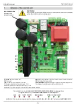
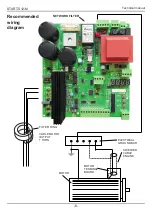
Scheme of the control unit / wiring diagram
6
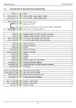
1.1
Description of the electrical connections
7
2
Use and functions of the control panel
8
2.1
State of the control unit
2.2
Settings and parameters
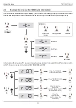
2.3
Example how to use the MENU
and information
9
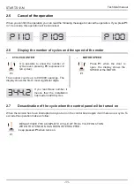
2.4
Set up a password for programming
10
2.5
Cancel of the operation
11
2.6
Display the number of cycles
and the speed of the motor
2.7
Desactivation of the cycle when the control
panel wil be turned on
3
Installation of the control unit
12
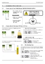
3.1
Connection of the TENSION and MOTOR
3.2
Connection of the lamp 230 Vac or 12 Vac
3.3
PRE-fl AShINg time
3.4
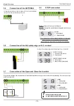
Connection of the ANTENNA
13
3.5
STOP connection
3.6
Connection of the 8k2 safety edge or N.C.
3.7
Connection of the Open and Close limit switch
3.8
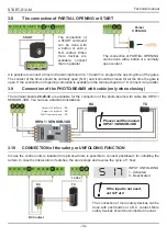
The connection of partial opening or START
14
3.9
Connection of the PhOTO-BEAMS with cable
3.10
CONNECTION of the safety
or UNfOlDINg fUNCTION
3.11
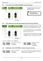
Connection of the PhOTO-BEAMS
15
3.12
Connection of the photo-beam
(activated when closing) with TEST
3.13
Deactivation of the PhOTOCEll A
3.14
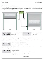
SlOW DOWN SWITCh
16
3.15
Connection of the brake and internal brake
4
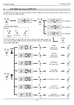
ACTIVATE the single OUTPUTS
17
5
Functions
18
5.1
logic of functions
5.2
Working time
19
5.3
Set SPEED and ACCElERATION
20
5.4
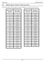
SChEME relation between SPEED
and fREQUENCY of the motor
21
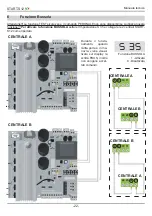
6
INTERLOCK Function
22
7
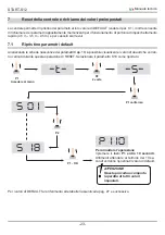
RESET of the control unit and restore of
factory default settings
23
7.1
Restore factory settings
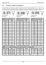
7.2
WARNINg of the SETTINg PARAMETERS
24
7.3
SAVE SET UP and ChECK of the parameters
8
LIST of the FUNCTIONS
26
9
Problems
29
10
Note
30
11
Declaration of CE conformity
31
Index
Summary of Contents for START-S12-M
Page 30: ...START S12 Manuale tecnico 30 10 Note ...
Page 63: ...START S12 M Technical manual 30 10 Note ...
Page 95: ...START S12 Technical manual 30 10 Note ...
Page 128: ...START S12 Instrución 31 10 Note ...
Page 129: ...START S12 Instrución 32 ...
Page 130: ...START S12 Instrución 33 ...
Page 164: ...START S12 Notice d emploi 31 10 Note ...
Page 165: ...START S12 Notice d emploi 32 ...
Page 166: ...START S12 Notice d emploi 33 ...

