ON
1
2
3
4
KE
ON
1
2
3
4
KE
MIN
POWER IR
MAX
ON
1
2
3
4
KE
ON
1
2
34
KE
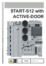
N.O.
input for Power Supply
12÷30 Vdc
+
-
Power ON
BUZZER
OFF ON
RUN
OFF = OK
1 FlASh= ERROR
2 FlAShES= A lOT OF ERRORS
FiX liGhT: AlARM
Setting the number of modules
diP1: Planning intervention time
diP 2: Not used
diP3: activate the beam of the
limit switch when diP4B is in ON
diP4: activate the self-exclusion
with Encoder
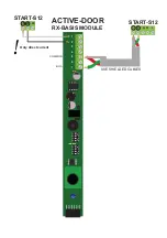
TX/RX iNSidE MOdUlE
+ power supply
- power supply
OUTPUT for allarm contact:
500mA Max
COMMON
OUTPUT for synchronisation
OUTPUT for BUS or ENCOdER
1
2
3
4
5
6
7
RX
TX
1
2
3
4
+ power supply
- power supply
COMMON
iNPUT for
synchronisation
POWER OF ThE
TRANSMiTTER
Power ON
RUN
diP3B:Activate the beam
of the limit switch.
In the basis of the RX
DIP3B and DIP4B have
to be in ON position
DIPB
DIPB
USE ShiEldEd CABlES
ATTENTION: DIP SWITCH FOR SET UP
OF THE SELF-EXCLUSION
diP4B BASiS RX -> ON
diP4B on ThE RX MOdUlES -> ON
diP3B->ON on ThE BASiS OF ThE RX: if
you need the limit switch in the basis of the
beam.
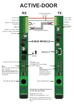
ACTIVE-DOOR
BASIS MODULE
TX/RX iNSidE MOdUlE
Summary of Contents for START-S12-M
Page 30: ...START S12 Manuale tecnico 30 10 Note ...
Page 63: ...START S12 M Technical manual 30 10 Note ...
Page 95: ...START S12 Technical manual 30 10 Note ...
Page 128: ...START S12 Instrución 31 10 Note ...
Page 129: ...START S12 Instrución 32 ...
Page 130: ...START S12 Instrución 33 ...
Page 164: ...START S12 Notice d emploi 31 10 Note ...
Page 165: ...START S12 Notice d emploi 32 ...
Page 166: ...START S12 Notice d emploi 33 ...

