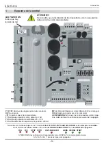
P1
P2
P3
DIP
12 13 14 15 16 17 18 19 20 21 22 23
28 29 30
24 25 26 27
FR1
FR2
MF3
MF2
MF1
FUSE 2
1.6 A
FUSE 1
10 A
LED
WARNING
FUSE 3
200 mA
1 2 3
4 5
6 7
P1
P2
P3
DIP
12 13 14 15 16 17 18 19 20 21 22 23
28 29 30
24 25 26 27
FR1
FR2
MF3
MF2
MF1
FUSE 2
1.6 A
FUSE 1
10 A
LED
WARNING
FUSE 3
200 mA
1 2 3
4 5
6 7
START-S12
Technical manual
-22-
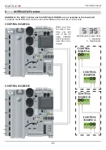
WARNING
: The TEST function and the PARTIAL
OPENING
are not available in this function!!!
To activate the INTERLOCK function use function
S35
and connect the 2 control units.
6
INTERLOCK Function
S 35
INTERLOCK FUNCTION
1 - Activated
0 - Deactivated
CONTROL BOARD A
CONTROL BOARD B
When one con-
trol uniti is wor-
king, you can
see in the di-
splay FBUSS,
and it cannot ac-
cept other com-
mands.
CONTROL
BOARD A
CONTROL
BOARD B
CONTROL
BOARD B
24 25 26 27
24 25 26 27
8 9 10 11
8 9 10 11
CONTROL
BOARD A
Summary of Contents for START-S12-M
Page 30: ...START S12 Manuale tecnico 30 10 Note ...
Page 63: ...START S12 M Technical manual 30 10 Note ...
Page 95: ...START S12 Technical manual 30 10 Note ...
Page 128: ...START S12 Instrución 31 10 Note ...
Page 129: ...START S12 Instrución 32 ...
Page 130: ...START S12 Instrución 33 ...
Page 164: ...START S12 Notice d emploi 31 10 Note ...
Page 165: ...START S12 Notice d emploi 32 ...
Page 166: ...START S12 Notice d emploi 33 ...

