Ricoh A230 Service Manual Download Page 1052

Tech Service Bulletin No. A230/A231/A232 – 037
Page 3 of 4

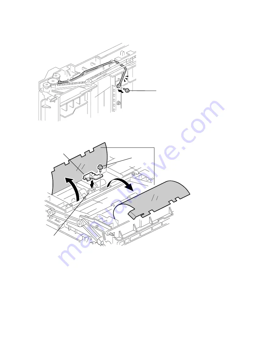
5. Route the Harness under the Drive Belt as shown in the illustration, taking up any

slack.

6. Secure the other end of the Harness with the Screw [E] that secures the Stay.


7.  Peel back the 2 strips of Mylar [A] attached to the Stay as shown in the illustration above.
8.  Peel back the two-sided tape remaining on the Stay (approximately 4cm total,

   centered around the Sensor [B]).

9.  Remove the Screw [C] (securing the Stay) that is closest to the Sensor.
10.  Place the new Plate Spring [D] (A6883914) over the Sensor, return the Mylar and

   fasten with the Screw removed in step 9.

NOTE

: Since there is a possibility of the roller slipping, clean the three Transport Rollers with alcohol or a

damp cloth.

Continued…

[A]

[C]

[D]

[B]

[E]

Summary of Contents for A230

Page 1: ...SERVICE MANUAL 000861MIU A230 A231 A232 RICOH GROUP COMPANIES ...

Page 2: ...SERVICE MANUAL A230 A231 A232 RICOH GROUP COMPANIES ...

Page 3: ...A230 A231 A232 SERVICE MANUAL 000861MIU ...

Page 4: ......

Page 5: ...ERMISSION OF RICOH CORPORATION All product names domain names or product illustrations including desktop images used in this document are trademarks registered trademarks or the property of their respective companies They are used throughout this book in an informational or editorial fashion only and for the benefit of such companies No such use or the use of any trade name or web site is intended...

Page 6: ......

Page 7: ...ation Users of this manual should be either service trained or certified by successfully completing a Ricoh Technical Training Program Untrained and uncertified users utilizing information contained in this service manual to repair or modify Ricoh equipment risk personal injury damage to property or loss of warranty protection Ricoh Corporation WARNING ...

Page 8: ......

Page 9: ...RICOH SAVIN A230 3235s Aficio 340 9935D A231 3235 Aficio 350 9935DP A232 3245 Aficio 450 9945P DOCUMENTATION HISTORY REV NO DATE COMMENTS 5 98 Original Printing 1 6 98 Revised pages 2 1 99 G909 G912 Addition 3 5 99 A695 Addition Rev 5 15 99 ...

Page 10: ......

Page 11: ... 9 2 DESCRIPTIONS 1 19 2 DETAILED SECTION DESCRIPTIONS 2 1 2 1 SCANNING 2 1 2 1 1 OVERVIEW 2 1 2 1 2 SCANNER DRIVE 2 2 2 1 3 ORIGINAL SIZE DETECTION IN PLATEN MODE 2 3 2 2 IMAGE PROCESSING 2 5 2 2 1 OVERVIEW 2 5 2 2 2 SBU 2 6 2 2 3 AUTO IMAGE DENSITY ADS 2 7 2 2 4 IPU IMAGE PROCESSING UNIT 2 8 Overview 2 8 Image processing path 2 9 SP modes for each image process 2 10 Auto shading 2 12 Background ...

Page 12: ...s bypass tray only 2 37 2 6 5 TONER SUPPLY 2 38 Toner bottle replenishment mechanism 2 38 Toner supply mechanism 2 39 2 6 6 TONER DENSITY CONTROL 2 40 Overview 2 40 Toner density control flow chart 2 40 Sensor control mode 2 41 Image Pixel Count Control Mode 2 42 2 6 7 TONER NEAR END END DETECTION 2 43 Toner near end end detection flow chart 2 43 2 6 8 TONER END RECOVERY 2 45 Toner end recovery fl...

Page 13: ... SAVER MODE 2 71 Entering the energy saver mode 2 71 What happens in energy saver mode 2 71 Return to stand by mode 2 71 2 11 3 LOW POWER MODE 2 72 Entering the low power mode 2 72 What happens in low power mode 2 72 Return to stand by mode 2 72 2 11 4 AUTO OFF MODE 2 73 Entering auto off mode 2 73 What happens in auto off mode 2 73 Returning to stand by mode 2 73 2 11 5 NIGHT MODE 2 74 Entering n...

Page 14: ... 41 3 11 2 INSTALLATION PROCEDURE 3 42 3 12 1 000 SHEET FINISHER INSTALLATION 3 44 3 12 1 ACCESSORY CHECK 3 44 3 12 2 INSTALLATION PROCEDURE 3 45 3 13 3 000 SHEET FINISHER INSTALLATION 3 48 3 13 1 ACCESSORY CHECK 3 48 3 13 2 INSTALLATION PROCEDURE 3 49 3 14 PUNCH UNIT INSTALLATION 3 52 3 14 1 ACCESSORY CHECK 3 52 3 14 2 INSTALLATION PROCEDURE 3 53 3 15 PLATEN COVER INSTALLATION 3 56 3 16 IMAGE ENH...

Page 15: ...M PARAMETER AND DATA LISTS SMC LISTS 4 57 4 2 7 NIP BAND WIDTH ADJUSTMENT SP1 109 4 58 4 2 8 MEMORY ALL CLEAR SP5 801 4 59 4 2 9 SOFTWARE RESET 4 60 4 2 10 SYSTEM SETTING AND COPY SETTING UP MODE RESET 4 60 System Setting Reset 4 60 Copy Setting Reset 4 60 4 3 PROGRAM DOWNLOAD 4 61 Downloading to the BICU 4 61 Download from BICU to Flash Memory Card 4 63 4 4 USER PROGRAM MODE 4 65 4 4 1 HOW TO ENT...

Page 16: ...23 6 4 DEVELOPMENT 6 24 6 4 1 DEVELOPMENT UNIT 6 24 6 4 2 DEVELOPMENT FILTER 6 25 6 4 3 DEVELOPMENT ROLLER 6 25 6 4 4 DEVELOPER 6 26 6 4 5 TD SENSOR 6 27 6 5 TRANSFER UNIT 6 28 6 5 1 TRANSFER BELT UNIT 6 28 6 5 2 TRANSFER BELT 6 29 6 5 3 TRANSFER BELT CLEANING BLADE TONER OVERFLOW SENSOR 6 30 Transfer Belt Cleaning Blade 6 30 Toner Overflow Sensor 6 30 6 5 4 RIGHT COVER 6 31 6 6 PAPER FEED 6 32 6 ...

Page 17: ...51 6 11 1 PRINTING 6 51 Registration Leading Edge Side to Side 6 51 Blank Margin 6 52 Main Scan Magnification 6 52 Parallelogram Image Adjustment 6 53 6 11 2 SCANNING 6 54 Registration Platen Mode 6 54 Magnification 6 54 Scanner Skew Image Adjustment 6 55 6 11 3 ADF IMAGE ADJUSTMENT 6 56 Registration 6 56 7 TROUBLESHOOTING 7 1 7 1 SERVICE CALL CONDITIONS 7 1 7 1 1 SUMMARY 7 1 7 1 2 SC CODE DESCRIP...

Page 18: ... 11 3 4 FUSES 8 11 4 REPLACEMENT AND ADJUSTMENT 8 12 4 1 COVER REPLACEMENT 8 12 Right Cover 8 12 Rear Cover 8 12 4 2 ROLLER REPLACEMENT 8 13 4 2 1 PAPER FEED SEPARATION AND PICK UP ROLLERS 8 13 Pick up Roller 8 13 Paper Feed Roller 8 13 Separation Roller 8 13 4 3 TRAY MOTOR REPLACEMENT 8 14 4 4 PAPER FEED AND RELAY CLUTCH REPLACEMENT 8 15 4 5 PAPER FEED UNIT REPLACEMENT 8 16 Upper Paper Feed Unit ...

Page 19: ...Rear Cover 9 10 Right Lower Cover 9 10 Upper Cover 9 10 4 2 ROLLER REPLACEMENT 9 11 4 2 1 PAPER FEED SEPARATION AND PICK UP ROLLERS 9 11 Pick up Roller 9 11 Paper Feed Roller 9 11 Separation Roller 9 11 4 3 TRAY LIFT AND PAPER END SENSOR REPLACEMENT 9 12 Tray Lift Sensor 9 12 Paper End Sensor 9 12 4 4 RELAY SENSOR REPLACEMENT 9 13 4 5 SIDE FENCE POSITION CHANGE 9 14 BY PASS A689 1 OVERALL MACHINE ...

Page 20: ...LL MACHINE INFORMATION 11 1 1 1 SPECIFICATIONS 11 1 1 2 MECHANICAL COMPONENT AND DRIVE LAYOUT 11 2 1 3 ELECTRICAL COMPONENT LAYOUT 11 3 1 4 ELECTRICAL COMPONENT DESCRIPTION 11 3 2 DETAILED DESCRIPTIONS 11 4 2 1 BASIC OPERATION 11 4 3 REPLACEMENT AND ADJUSTMENT 11 5 3 1 COVER REMOVAL 11 5 Front Cover 11 5 Upper Cover 11 5 Rear Cover 11 5 3 2 PAPER SENSOR REPLACEMENT 11 6 3 3 ENTRANCE AND PAPER LIMI...

Page 21: ...E SIDED ORIGINAL MODE 12 16 2 8 4 ORIGINAL EXIT MECHANISM DOUBLE SIDED ORIGINAL MODE 12 17 2 9 STAMP 12 18 2 10 JAM CONDITIONS 12 19 2 11 TIMING CHARTS 12 20 2 11 1 A4 SIDEWAYS ONE SIDED ORIGINAL 3 ORIGINALS 12 20 2 11 2 A4 SIDEWAYS TWO SIDED ORIGINAL 2 ORIGINALS 12 21 3 SERVICE TABLES 12 22 3 1 DIP SWITCHES 12 22 3 2 TEST POINTS 12 22 3 3 VARIABLE RESISTORS 12 22 3 4 FUSES 12 22 4 REPLACEMENT AND...

Page 22: ...2 1 JUNCTION GATE MECHANISM 13 4 To the Exit Tray or Bridge Unit for the Upper Tray Left Tray or Finisher 13 4 To the 1 bin Tray 13 4 To the Duplex Unit 13 4 3 REPLACEMENT AND ADJUSTMENT 13 5 3 1 EXIT SENSOR COPIER REPLACEMENT 13 5 DUPLEX A687 1 OVERALL MACHINE INFORMATION 14 1 1 1 SPECIFICATIONS 14 1 1 2 MECHANICAL COMPONENT LAYOUT 14 2 1 3 ELECTRICAL COMPONENT LAYOUT 14 3 1 4 ELECTRICAL COMPONEN...

Page 23: ...16 1 1 1 SPECIFICATIONS 16 1 1 2 MECHANICAL COMPONENT LAYOUT 16 2 1 3 ELECTRICAL COMPONENT LAYOUT 16 3 1 4 ELECTRICAL COMPONENT DESCRIPTIONS 16 4 1 5 DRIVE LAYOUT 16 6 2 DETAILED DESCRIPTIONS 16 7 2 1 JUNCTION GATE MECHANISM 16 7 Staple mode 16 7 No staple mode 16 7 2 2 JOGGER UNIT PAPER POSITIONING MECHANISM 16 8 2 3 EXIT GUIDE PLATE OPEN CLOSE MECHANISM 16 9 2 4 STAPLER 16 10 2 5 FEED OUT MECHAN...

Page 24: ... COMPONENT LAYOUT 17 3 1 3 ELECTRICAL COMPONENT LAYOUT 17 4 1 4 ELECTRICAL COMPONENT DESCRIPTION 17 5 1 5 DRIVE LAYOUT 17 7 2 DETAILED DESCRIPTIONS 17 8 2 1 TRAY AND STAPLER JUNCTION GATE MECHANISM 17 8 Normal mode 17 8 Sort stack mode 17 8 Staple mode 17 8 2 2 JOGGER UNIT PAPER POSITIONING MECHANISM 17 9 Vertical Paper Alignment 17 9 Horizontal Paper Alignment 17 9 2 3 STAPLER UNIT MOVEMENT MECHA...

Page 25: ...t Shift Tray Cover 17 23 Rear Shift Tray Cover 17 23 4 2 POSITIONING ROLLER REPLACEMENT 17 24 4 3 ALIGNMENT BRUSH ROLLER REPLACEMENT 17 25 4 4 SENSOR REPLACEMNT 17 26 4 4 1 STACK HEIGHT SENSOR 1 AND 2 17 26 4 4 2 UPPER TRAY PAPER LIMIT AND EXIT SENSOR 17 27 Upper Tray Paper Limit Sensor 17 27 Upper Tray Exit Sensor 17 27 4 4 3 SHIFT TRAY EXIT SENSOR 17 28 4 4 4 ENTRANCE AND STAPLER TRAY ENTRANCE S...

Page 26: ...4 1 SWAPBOX RESOURCE CONFLICT 18 7 4 11 IRQ AND I O ADDRESS 18 7 4 1 2 MEMORY ADDRESS 18 7 4 2 FAILED TO OPEN PCCARD ERRORS 18 8 4 2 1 TIMELAG TO LOADING DRIVER 18 8 4 2 3 RESOURCE CONFLICT 18 8 4 3 INVALID DYNAMIC LINK CALL FROM SWAPENUM ERROR 18 9 4 4 SWAPFTL PROBLEM WITH NOTEBOOK COMPUTERS 18 9 4 4 1 WINDOWS AND PC CARD DRIVER VERSION 18 9 4 4 2 SYSTEM SUMMERY 18 9 4 5 COMPLETE UNINSTALL 18 10 ...

Page 27: ... 20 4 2 DETAILED DESCRIPTIONS 20 6 2 1 BASIC OPERATION 20 6 Proof Tray 20 6 Bridge Unit 20 6 Trays 20 6 2 2 PROOF TRAY SENSORS 20 7 2 2 1 PAPER SENSOR 20 7 2 2 2 PAPER OVERFLOW SENSOR 20 7 2 3 TRAY SENSORS 20 8 2 3 1 PAPER SENSOR 20 8 2 3 2 PAPER OVERFLOW SENSOR 20 8 2 3 3 TRAY EXIT SENSOR 20 8 2 4 TIMING CHART AND MISFEED DETECTION 20 9 3 INSTALLATION PROCEDURE 20 11 3 1 MAILBOX G909 20 11 3 1 1 ...

Page 28: ...1 SPECIFICATIONS 21 1 1 2 SOFTWARE 21 1 1 2 1 SCANNER DRIVE 21 1 2 DETAILED SECTION DESCRIPTIONS 21 2 2 1 HARDWARE OVERVIEW 21 2 2 2 IMAGE SCANNING 21 3 2 3 SCANNER FUNCTIONS 21 4 2 3 1 SELF DIAGNOSTICS 21 4 2 3 2 ENTERING THE SCANNER MODE 21 4 2 3 3 EXITING THE SCANNER MODE 21 4 2 3 4 SCSI ID 21 4 3 INSTALLATION PROCEDURE 21 5 4 TROUBLESHOOTING 21 10 4 1 SELF DIAGNOSTICS 21 10 4 1 1 ERROR INDICAT...

Page 29: ...E TERM OF SERVICE CALLS 2 4 2 2 SCANNING FEATURES 2 5 2 2 1 SUB SCAN LENGTH CORRECTION USING ADF 2 5 2 2 2 PAGE SPLIT TRANSMISSION BOOK TRANSMISSION 2 7 2 2 3 IMAGE ROTATION BEFORE TRANSMISSION 2 8 2 3 PRINTING FEATURES 2 10 2 3 1 PAPER SIZE SELECTION 2 10 WIDTH PRIORITY AND LENGTH PRIORITY 2 10 IMAGE ROTATION BEFORE PRINTING 2 10 SUB SCAN REDUCTION AND PAGE SEPARATION 2 11 PAGE REDUCTION 2 14 TWO...

Page 30: ...SERVICE MONITOR REPORT FUNCTION 04 4 5 4 1 8 G3 PROTOCOL DUMP LIST FUNCTION 05 4 6 4 1 9 G4 PROTOCOL DUMP LIST FUNCTION 05 4 6 4 1 10 RAM DISPLAY AND REWRITE FUNCTION 06 4 7 4 1 11 NCU PARAMETERS FUNCTION 06 4 7 4 1 12 RAM DUMP FUNCTION 06 4 8 4 1 13 RAM CLEAR FUNCTION 07 4 8 4 1 14 HARD DISK FUNCTION 08 4 9 4 1 15 SERVICE STATION FAX NUMBER FUNCTION 09 4 9 4 1 16 SERIAL NUMBER FUNCTION 10 4 9 4 1...

Page 31: ...ASH CARD BACKUP 5 4 5 4 ROM UPDATE 5 6 5 4 1 FCU ROM DOWNLOAD 5 6 5 4 2 FCU ROM UPLOAD 5 8 5 4 3 MODEM ROM DOWNLOAD 5 9 5 5 SRAM DATA BACKUP AND RESTORE 5 11 5 5 1 SRAM BACKUP TO A FLASH MEMORY CARD 5 11 5 5 2 SRAM RESTORE FROM A FLASH MEMORY CARD 5 12 5 6 DATA ADDRESS RANGES ON THE CARD 5 13 5 6 1 FCU AND BICU ROM DATA 5 13 5 6 2 MODEM ROM AND SRAM DATA 5 13 6 TROUBLESHOOTING 6 1 6 1 ERROR CODES ...

Page 32: ... 6 Primary Channel 6 16 Control Channel Post Message Sh 6 16 Control Channel Post Message PPh 6 17 Control Channel Recovery AC 6 17 V 34 End 6 17 6 3 FAX SC CODES 6 18 6 3 1 SC1201 6 18 6 3 2 SC1202 6 18 6 3 3 SC1207 6 19 6 3 4 SC1802 1811 1815 6 19 6 3 5 FAX SC CODE TABLE 6 20 6 4 FIRMWARE HISTORY 6 21 6 4 1 A693 FIRMWARE MODIFICATION HISTORY 6 21 Rev 05 2000 ...

Page 33: ...YER MANAGEMENT 3 2 3 1 2 D CHANNEL LAYER 1 3 2 3 1 3 D CHANNEL LINK LAYER 3 2 3 1 4 D CHANNEL NETWORK LAYER 3 3 3 1 5 B CHANNEL LINK LAYER 3 3 3 1 6 B CHANNEL NETWORK LAYER 3 4 3 1 7 TRANSPORT LAYER 3 4 3 1 8 SESSION LAYER 3 5 3 1 9 DOCUMENT LAYER 3 6 3 1 10 PRESENTATION LAYER 3 6 3 2 G4CCU STATUS CODES 3 7 3 2 1 LAYER 1 PHYSICAL LAYER 3 7 3 2 2 LAYER 2 LINK LAYER 3 7 3 2 3 NETWORK LAYER LAYER 3 3...

Page 34: ...Reading the Sample Dump List A 4 Layer 1 Status A 7 APPENDIX B B G4 PARAMETER LOCATIONS B 1 1 1 INITIAL PROGRAMMING ITEMS COMPARISON LIST B 1 1 2 SWITCH LOCATIONS COMPARISON LIST B 2 APPENDIX C C CONDITIONS FOR RECEIVING A CALL C 1 Rev 08 98 ...

Page 35: ......

Page 36: ...s the copier starts making copies as soon as the warm up period is completed 6 The inside and the metal parts of the fusing unit become extremely hot while the copier is operating Be careful to avoid touching those components with your bare hands HEALTH SAFETY CONDITIONS 1 Toner and developer are non toxic but if you get either of them in your eyes by accident it may cause temporary eye discomfort...

Page 37: ...es and Radiological Health CDRH prohibits the repair of laser based optical units in the field The optical housing unit can only be repaired in a factory or at a location with the requisite equipment The laser subsystem is replaceable in the field by a qualified Customer Engineer The laser chassis is not repairable in the field Customer engineers are therefore directed to return all chassis and la...

Page 38: ...NS BY PASS A689 DETAILED DESCRIPTIONS A693 SwapBox and SwapFTL A230 INSTALLATION 1 BIN TRAY A684 INSTALLATION A693 NINE TRAY MAILBOX AND BRIDGE UNIT G909 G912 A230 SERVICE TABLES AUTO DOCUMENT FEEDER A680 SERVICE TABLES A693 SCANNER KIT A695 A230 PREVENTIVE MAINTENANCE INTERCHANGE UNIT A690 REPLACEMENT AND ADJUSTMENT A693 A230 REPLACEMENT AND ADJUSTMENT DUPLEX A687 TROUBLESHOOTING A693 A230 TROUBL...

Page 39: ......

Page 40: ...OVERALL MACHINE INFORMATION ...

Page 41: ......

Page 42: ...lb The duplex unit and by pass feed unit are not standard for A230 Reproduction Ratios 7R5E Metric version 400 200 141 122 115 100 93 87 82 71 65 50 25 Inch version 400 200 155 129 121 100 93 85 78 73 65 50 25 7R5E Metric version 400 200 141 122 115 100 93 87 82 71 65 50 35 Inch version 400 200 155 129 121 100 93 85 78 73 65 50 32 Zoom Both versions 25 to 400 in 1 steps Metric version 35 to 400 in...

Page 43: ... Tray 500 sheets up to 56 mm 2 2 x 2 By pass Feed 50 sheets up to 5 5 mm 0 2 The by pass feed unit is not standard for A230 Copy Tray Capacity A4 11 x 8 5 500 sheets A3 B4 8 5 x 14 11 x 17 250 sheets Standard copy tray Toner Replenishment Cartridge exchange 700 g cartridge Toner Yield 27k copies A4 sideways 6 full black 1 to 1 copying ADS mode Power Source North America 120V 60Hz More than 12 A Eu...

Page 44: ...Less than 1 05 kW Less than 1 15 kW Stand by Less than 220 W h Less than 240 W h Energy Saver Level 1 Ave 160 W h Ave 180 W h Energy Saver Level 2 Ave 154 W h Ave 168 W h Auto Shut Off Ave 12 W h Ave 12 W h System 115 V machine A230 A231 A232 Note Maximum Less than 1 44 kW Less than 1 44 kW Copying Less than 1 2 kW Less than 1 35 kW Warm up Less than 1 05 kW Less than 1 15 kW Stand by Less than 22...

Page 45: ...A 44 dB A 2 Sound Pressure Level at the Operator s Position Copying A230 A231 A232 52 dB A 56 dB A 60 dB A 62 dB A Stand by A230 A231 A232 27 dB A 27 dB A 28 dB A 28 dB A NOTE 1 The above measurements were made in accordance with ISO 7779 2 Full system measurements do not include the optional fax unit and the printer controller 3 In the above stand by condition the polygon motor is not rotating ...

Page 46: ...finisher or optional external output tray If the sub scan length is more than 330 mm the exit tray is as shown below if the relevant options have been installed Installed options Exit tray for paper longer than 330 mm Bridge unit Finisher 1 000 sheet Int Tray A Bridge unit Finisher 3 000 sheet Ext Tray C The finisher upper tray Bridge unit optional ext output tray Ext Tray C Ext output tray A231V5...

Page 47: ...MACHINE CONFIGURATION 1 6 A230 A231 A232 SM 1 3 MACHINE CONFIGURATION 1 3 1 SYSTEM COMPONENTS A231V502 WMF 2 3 4 5 6 11 1 2 13 14 1 7 8 9 10 ...

Page 48: ...ge Unit Option A688 13 1000 sheet Finisher Option A681 11 3000 sheet Finisher Option A232 only A697 10 Punch Unit Option for 3000 sheet Finisher A812 17 3 holes A812 27 2 holes External Output Tray Option A825 12 Electrical Sort Kit 8 MB Memory Option A230 only A818 Image Enhancement Kit HDD Option A691 Key Counter Bracket Option A674 14 Copy Expansion Box Option A692 Fax Unit Option A693 ISDN Uni...

Page 49: ...es the interchange unit Bridge Unit 1 000 sheet Finisher Requires the paper tray unit and bridge unit 3 000 sheet Finisher X X Requires the paper tray unit and bridge unit Punch Unit X X Requires the 3000 sheet finisher External Output Tray Requires the bridge unit Electrical Sort Kit 8 MB Memory Image Enhancement Kit HDD Requires the electrical sort kit 8 MB Key Counter Bracket Expansion Box It i...

Page 50: ...rall Information MECHANICAL COMPONENT LAYOUT 1 9 SM A230 A231 A232 1 4 MECHANICAL COMPONENT LAYOUT A231V503 WMF 1 10 11 12 13 14 15 16 17 18 19 20 21 22 24 25 27 23 28 29 30 31 2 3 4 5 6 7 8 9 26 Rev 7 98 ...

Page 51: ...r 11 Exit Junction Gate 12 Hot Roller 13 Pressure Roller 14 Transfer Belt Cleaning Blade 15 OPC Drum 16 Transfer Belt 17 Registration Roller 18 Upper Relay Rollers 19 Feed Roller 20 Separation Roller 21 Pick up Roller 22 Bottom Plate 23 Development Unit 24 Charge Roller 25 Fθ Mirror 26 Barrel Toroidal Lens BTL 27 Polygonal Mirror Motor 28 Laser Unit 29 Toner Supply Bottle Holder 30 Exit Roller 31 ...

Page 52: ...11 SM A230 A231 A232 1 5 PAPER PATH A230v102 wmf Optional ARDF 1000 sheet Finisher Optional 1 bin Tray Optional Paper Tray Unit Optional Duplex Unit Optional Interchange Unit Optional By pass Feed Unit Optional Bridge Unit Optional LCT ...

Page 53: ...drum charge roller development roller and transfer belt PCB6 9 SBU Sensor Board Unit Contains the CCD and outputs a video signal to the BICU board PCB7 7 SIB Scanner Interface Board Controls the scanner carriages and passes signals from the scanner unit to the BICU board PCB8 11 Operation Panel Controls the LCD and LED matrix and monitors the key matrix PCB9 4 Lamp Stabilizer Provides dc power to ...

Page 54: ...e original This is one of the APS Auto Paper Select sensors S6 21 LD Unit Home Position Informs the CPU when the LD unit is at the home positon S7 17 Toner Density TD Detects the amount of toner inside the development unit S8 24 Paper Exit Detects misfeeds S9 27 Registration Detects the leading edge of the copy paper to determine the stop timing of the paper feed clutch and detects misfeeds S10 26...

Page 55: ... Safety Cuts the 5VLD and 24V dc power line and detects whether the front cover is open or not SW5 10 Operation Switch Provides power for machine operation The machine still has power if this switch is off Magnetic Clutches CL1 39 Transfer Belt Controls the touch and release movement of the transfer belt unit CL2 40 Registration Drives the registration rollers CL3 44 Relay Drives the relay rollers...

Page 56: ...ounters CO1 50 Total Keeps track of the total number of prints made CO2 N A Key option Used for control of authorized use If this feature is enabled for copying copying will be impossible until it is installed It can also be enabled for fax and printer modes separately Others CB1 57 Circuit Breaker 220 240V only Provides back up high current protection for electrical components LSD 23 Laser Synchr...

Page 57: ... 1 7 DRIVE LAYOUT 1 Scanner Drive Motor 2 Transfer Belt Clutch 3 Registration Clutch 4 Upper Paper Feed Clutch 5 Lower Paper Feed Clutch 6 Relay Clutch 7 Main Motor A230V108 WMF Scanner Fusing Transfer Development PCU Drive 1 2 3 4 5 6 7 ...

Page 58: ... the original passes to the CCD where it is converted into an analog data signal This data is converted to a digital signal processed and stored in the memory At the time of printing the data is retrieved and sent to the laser diode For multi copy runs the original is scanned once only and stored to the memory A231v500 WMF A230V101 WMF 1 2 8 7 6 5 4 3 9 ...

Page 59: ...ace and the transfer belt at the proper time to align the copy paper and the developed image on the drum surface Then the transfer bias roller applies a high positive charge to the reverse side of the paper through the transfer belt This positive charge pulls the toner particles from the drum surface onto the paper At the same time the paper is electrically attracted to the transfer belt 6 PAPER S...

Page 60: ... Stabi lizer Scanner Motor APS Sensors Polygon Motor Mother Board Duplex IOB PSU Counter Fans Sensors Clutches 1 bin Tray Bridge Unit Main Motor High Voltage Supply Exposure Lamp LD Posi tioning Motor LD H P Sensor Paper Feed Controller PFB Paper Tray Unit LCT Clutches Sensors Fax Controller Printer Controller Finisher LSD SIFB Standard Option ...

Page 61: ...gh voltage supply board Serial interface with peripherals Fusing control 3 SBU Sensor Board Unit The SBU receives the analog signals from the CCD and converts them into digital signals 4 SIB Scanner Interface Board This board controls the scanner motor and passes signals between the BICU board and the component parts of the scanner unit Also it transmits the video signals from the SBU to the BICU ...

Page 62: ...DETAILED SECTION DESCRIPTIONS ...

Page 63: ......

Page 64: ...mirror F The exposure lamp is energized by a dc supply to avoid uneven light intensity while the 1st scanner moves in the sub scan direction down the page The entire exposure lamp surface is frosted to ensure even exposure in the main scan direction across the page The light reflected by the reflector is of almost equal intensity in all directions to reduce shadows on pasted originals An optics an...

Page 65: ...231 or 230 mm s A232 during scanning The 2nd scanner speed is half that of the 1st scanner In reduction or enlargement mode the scanning speed depends on the magnification ratio The returning speed is always the same whether in full size or magnification mode The image length change in the sub scan direction is done by changing the scanner drive motor speed and in the main scan direction it is don...

Page 66: ... a reflective photosensor While the power is on these sensors are active and the original size data is always sent to the CPU However the CPU checks the data only when the platen cover sensor C is activated This is when the platen reaches about 15 cm above the exposure glass for example while it is being closed The main CPU can recognize the original size from the on off signals from the APS senso...

Page 67: ...original size This original size detection method eliminates the necessity for a pre scan and increases the machine s productivity However if the by pass feeder is used note that the machine assumes that the copy paper is lengthwise For example if A4 sideways paper is placed on the by pass tray the machine assumes it is A3 paper and scans a full A3 area disregarding the original size sensors Howev...

Page 68: ...d into two image processing blocks the IPU Image Processing Unit and the memory control IC These two ICs do the following IPU Auto shading filtering magnification γ correction and gradation processing Memory controller Image compression decompression and memory address control binary picture processing mode only Finally the BICU board sends the video data to the LD drive board SIB SIFB LD Driver I...

Page 69: ...position A230 and A231 only Analog signals for odd and even pixels from the CCD are merged by a switching device 3 Signal Amplification The analog signal is amplified by operational amplifiers in the AGC circuit The maximum gains of the operational amplifiers are controlled by the CPU on the BICU board After the above processing the analog signals are converted to 8 bit signals by the A D converte...

Page 70: ...vel the IPU determines the reference value for A D conversion for the scan line Then the IPU sends the reference value to the A D controller on the SBU When an original with a gray background is scanned the density of the gray area is the peak white level density Therefore the original background will not appear on copies Because peak level data is taken for each scan line ADS corrects for any cha...

Page 71: ... shading 2 Filtering MTF and smoothing 3 Magnification 4 γ correction 5 Grayscale processing 6 Binary picture processing 7 Error diffusion 8 Dithering 9 Video path control 10 Test pattern generation The image data then goes to either the LDDR or the memory control IC GA 1 depending on the selected copy modes LD1 LD2 IPU GA 1 DRAM Fax Controller Printer Controller SBU SIB BICU LDDR M B S I F B HDD ...

Page 72: ...γ Corre ction Error diffusion Letter Photo Auto Shading Smoo thing Magnifi cation γ Corre ction 8 x 8 Dithering Photo Auto Shading Background Independent Dot Erase MTF Magnifi cation γ Corre ction Grayscale Letter Auto Shading MTF Magnifi cation γ Corre ction Error diffusion Letter Photo Auto Shading Smoo thing Magnifi cation γ Corre ction 6 x 6 Dithering Photo Auto Shading Background Independent ...

Page 73: ...dot erase level SP4903 41 44 MTF filter coefficient SP4903 50 53 MTF filter strength SP2909 1 Main scan mag SP4904 12 Threshold level Letter Photo SP4903 35 Background erase level SP4903 30 Independent dot erase level SP4903 47 MTF filter coefficient SP4903 55 MTF filter strength SP2909 1 Main scan mag Photo SP4903 36 Background erase level SP4904 3 Filter type smoothing or MTF SP4903 16 Smoothing...

Page 74: ...xt photo auto separation SP4904 7 Gradation type in text areas SP4904 8 Gradation type in photo areas Photo SP4903 36 Background erase level SP4904 3 Filter type smoothing or MTF SP4903 16 Smoothing filter coefficient SP4903 15 MTF filter coefficient SP4903 24 MTF filter strength SP2909 1 Main scan mag SP4904 2 Dither matrix type Copied Original SP4903 37 Background erase level SP4903 32 Independe...

Page 75: ...de However it can be enabled for other modes by SP mode Usually dirty background is erased using the Auto Image Density ADS function However sometimes dirty background areas will still appear These can be erased by this function If any low image density data which is lower than a threshold level remains after auto shading this data will be changed to 0 white The threshold level can be changed with...

Page 76: ...Each SP mode has 16 levels as follows A The sum of the pixels at the edges SP mode value Function SP mode value Function 0 Disabled 8 Disabled 1 If A 16 the pixel is deleted 9 If A 16 density is reduced 2 If A 32 the pixel is deleted 10 If A 32 density is reduced 3 If A 48 the pixel is deleted 11 If A 48 density is reduced 4 If A 64 the pixel is deleted 12 If A 64 density is reduced 5 If A 80 the ...

Page 77: ...ficient for each mode can be adjusted with SP4 903 MTF Filter Coefficient SP4 903 11 15 17 19 41 47 Weak 11 8 2 1 9 0 5 4 10 7 3 6 Strong MTF Filter Strength SP4 903 20 27 50 53 55 Weak x0 25 x0 5 x1 x2 x4 Strong Smoothing Filter Coefficient SP4 903 16 Weak 7 6 0 5 2 1 3 4 Strong A stronger MTF filter leads to sharper lines A stronger smoothing filter leads to a greater degree of smoothing Refer t...

Page 78: ...has 256 output levels for each pixel When the optional image enhancement kit HDD is installed the binary picture processing mode cannot be selected 2 Binary picture processing This has only two output levels black and white and is used only in memory copying only without HDD and fax transmission 3 Error diffusion In text photo mode this is used with either grayscale processing or binary processing...

Page 79: ...age pixel so that the edges of characters and lines become clearer There is no SP mode adjustment for this unlike in some earlier models Binary picture processing Each video signal level is converted from 8 bit to 1 bit black and white image data in accordance with a threshold value The threshold value can be adjusted with SP 4 904 12 Error diffusion This is used only in text photo mode The error ...

Page 80: ...processing The matrix type can be selected with SP4 904 18 Line width correction This function is effective only in copied original mode Usually lines will bulge in the main scan direction as a result of the negative positive development system that is used in this model So pixels on edges between black and white areas are compared with adjacent pixels and if the pixel is on a line the line thickn...

Page 81: ...ransfer to the HDD FIFO memory and GA1 Controls the HDD DRAM 4 MB Stores compressed data in grayscale and binary picture processing mode Page memory 2 MB working area 2 MB SIMM memory 8 MB Stores compressed data with grayscale and binary picture processing mode In binary picture processing mode all the memory capacity is used for storing the image data At this time the DRAM is used for a working a...

Page 82: ...y Grayscale X X O X X O Image Rotation Binary Grayscale O X O O X O Key O O Possible in both binary and grayscale mode if this equipment is installed O X Possible only in binary mode if this equipment is installed X O Possible only in grayscale mode if this equipment is installed X X Not possible in either mode Example Multiple copy of multi page original is impossible with greyscale processing if...

Page 83: ...2 IC where the image data for a whole page is divided into many blocks the block size is 4 x 4 pixels as shown above left Then each block is compressed and sent to HDD DRAM and SIMM memory For printing the compressed data blocks from the HDD DRAM and SIMM memory go back to the GA2 IC This IC assigns these blocks to the proper positions for printing then the data blocks are decompressed In the imag...

Page 84: ... mode Usually binary picture processing generates jagged edges on characters as shown in the above left illustration The FCI reduces jagged edges of characters using the image smoothing process Whether or not the object pixel undergoes smoothing depends on the surrounding image data The smoothing process for the object pixel is done by changing the laser pulse positioning and the laser power ...

Page 85: ...le drum rotation controls the sub scan The combined strength of both beams is 0 336 mW A230 and A231 0 430 mW A232 on the drum surface at a wavelength of 780 nm The polygon motor speed is as follows Motor Speed rpm 1 line cycle µs Resolution Modes A230 A231 A232 A230 A231 A232 400 dpi Copy Fax Approx 14170 Approx 18110 353 276 600 dpi Printer Approx 21260 Approx 27170 235 184 391 2 dpi Fax image r...

Page 86: ...n mirror B through the cylindrical lens C and the shield glass D Each surface of the polygon mirror reflects two full main scan lines The laser beams go to the F theta mirror E mirror F and BTL barrel toroidal lens G Then these laser beams go to the drum through the toner shield glass H The laser synchronizing detector I determines the main scan starting position A231D501 WMF A B C D E F G H I ...

Page 87: ...ing through the photodiode PD Then they increase or decrease the current to the laser diode as necessary comparing it with the reference levels REF1 and REF2 This auto power control is done just after the machine is turned on and during printing while the laser diode is active The reference levels are adjusted on the production line Do not touch the variable resistors on the LDDR in the field VIDE...

Page 88: ...ygon motor rotation speed 2 To reduce the noise generated by the polygon motor 3 To reduce the frequency of the image data clock Two laser beams are transferred to the polygon mirror C through collimating lens D and prism E The two laser beams arrive on the drum surface about 2 mm away from each other in the main scan direction and about 0 06 mm at 400 dpi in the sub scan direction see the next pa...

Page 89: ... down This changes the position of the L2 laser beam L1 does not move Both LD unit positions are at fixed distances from the LD home position sensor D measured by motor pulses Usually the LD unit moves directly to the proper position However when the number of times that the resolution has changed reaches the value of SP2 109 5 the LD unit moves to the home position the home position sensor activa...

Page 90: ...hes located at the front cover and upper right cover These four switches are installed in series on the LD5 V line coming from the power supply unit PSU through the BICU board When the front cover or the upper right cover is opened the power supply to the laser diode is interrupted CN403 1 CN403 3 CN402 3 CN402 4 CN312 2 CN109 1 CN301 4 5V PSU BICU LDDR 5V LD5V LD1 LD2 Front Cover Safety Sw Upper ...

Page 91: ...omponents shown in the above illustration An organic photoconductor OPC drum diameter 60 mm is used in this machine 1 Toner Collection Coil 6 Transfer Entrance Guide 2 Toner Collection Plate 7 Charge Roller Cleaning Pad 3 Spur 8 Charge Roller 4 Pick off Pawl 9 Cleaning Blade 5 OPC Drum A230D301 WMF 1 2 3 4 5 6 7 8 9 ...

Page 92: ...iming belt C and the drum drive shaft D The main motor has a drive controller which outputs a motor lock signal when the rotation speed is out of the specified range The fly wheel E on the end of the drum drive shaft stabilizes the rotation speed this prevents banding and jitter from appearing on copies The A232 has two flywheels because of the higher speed A230D302 WMF A B C D E ...

Page 93: ... the drum The drum charge roller A always contacts the surface of the drum B to give it a negative charge The high voltage supply board C gives a negative dc voltage to the drum charge roller through the charge roller terminal D bias plate E and the rear roller bushing F This gives the drum surface a negative charge of 950V A231D525 WMF A B C D E F ...

Page 94: ...toner transferred to the drum This measurement is made immediately after the ID sensor pattern for toner density control Immediately after making ID sensor pattern A the charge roller voltage drops so that drum potential is reduced to 600V At the same time development bias goes back to 550V The drum potential is now slightly higher than the development bias so only a very small amount of toner tra...

Page 95: ...ction for paper width and thickness bypass tray only The bypass tray can be used for narrower paper than the paper trays Also thicker paper can be used as well as OHP sheets In these cases some copy quality problems may occur To deal with this the charge roller voltage can be increased for paper fed from the bypass tray The voltage corrections are adjusted with SP 2 914 1 and 2 The width threshold...

Page 96: ...drum charge roller A is always in contact with the drum it gets dirty easily So the cleaning pad B is also in contact with the drum charge roller all the time to clean the surface of the drum charge roller The pin C at the rear of the cleaning pad holder touches the cam gear D and this gear moves the cleaning pad from side to side This movement improves the cleaning New Vref Decision 1 10 9 8 3 2 ...

Page 97: ...1 OVERVIEW This machine uses a single roller development system A dual mixing roller mechanism is used for developer mixing 1 Drum 5 Mixing Auger 2 Development Roller 6 Development Filter 3 Paddle Roller 7 Doctor Blade 4 TD Sensor A230D401 WMF 1 2 3 4 5 6 7 ...

Page 98: ...r A drives the development roller B through a train of gears and the paddle roller gear C The development drive gears are helical gears These gears are quieter than normal gears When the development unit is pushed in the development drive shaft engages the paddle roller gear A230D402 WMF A B C ...

Page 99: ...velopment roller The developer that is spilt off by the doctor blade goes through the holes C in the outer paddle and is transported towards the rear by the inner auger While the dual mixing roller is moving the developer some developer also goes back to the development unit through the holes in the bottom of the paddle roller Both new toner from the toner bottle and recycled toner from the toner ...

Page 100: ...1 Correction for paper width and thickness bypass tray only The bypass tray can be used for narrower paper than the paper trays Also thicker paper can be used as well as OHP sheets In these cases some copy quality problems may occur To deal with this the development bias can be increased for paper fed from the bypass tray The voltage corrections are adjusted with SP 2 914 3 and 4 The width thresho...

Page 101: ... the cap F on the toner bottle is pulled away and kept in place by the chuck G The toner supply mechanism transports toner from the bottle to the development unit The toner bottle has a spiral groove H that helps move toner to the development unit When the bottle holder unit is pulled out to add a new toner bottle the following automatically occurs to prevent toner from scattering The chuck releas...

Page 102: ...des C First the toner falls down into the toner bottle holder The toner supply mylar blades transfer the toner to the slit D When the PCU is installed into the machine the shutter E under the PCU is opened by the development unit Then the toner falls down into the development unit through the slit and the shutter A231D505 WMF A230D452 WMF A B C D E ...

Page 103: ...g Vt 10 detection Toner supply motor turns on in reverse for 0 3 s GAIN determination Image pixel count mode GAIN 1 Toner supply motor on time calculation Vsp Vsg detection New Vtref determination Image pixel count K K 0 25 K K 0 5 K K 0 25 Has the following condition been detected 20 times Vtref Vt 10 Vtref 0 1 Vt 10 or K 1 5 Has the following condition been detected 10 times Vtref 0 2 Vt 10 or H...

Page 104: ...ds up the image data value of each pixel and converts the sum to a value between 0 and 255 The value would be 255 if the page was completely black Vt 10 detection The toner density in the developer is detected once every copy cycle The sensor output voltage Vt 10 is the average of the 10 most recent sensor output voltage readings Toner density measurement The machine compares Vt 10 and Vtref If Vt...

Page 105: ...riod can be changed using SP2 210 the default is 10 New Vtref determination Even if the toner concentration in the developer is kept constant by checking the TD sensor the toner potential chargeability and the image density both change with humidity and the amount of toner on the carrier Therefore the actual image density using the ID sensor output is also used as one of the factors for deciding t...

Page 106: ...s Toner near end Has Vtref Vt 10 been detected 40 times No No Yes No No Start copying each page Toner supply motor on time x2 Has Vtref Vt 10 been detected 20 more times Has Vtref Vt 10 been detected 20 more times Has Vtref Vt 10 been detected 40 times ID sensor check Vsp 2 0 V Have 90 copies been made since toner near end detection Toner end Toner supply motor turns while main motor turns Yes No ...

Page 107: ...hine has detected 40 times that Vt 10 is greater than Vtref the toner supply motor turns on for double the time that it would be with the previous formula If the toner concentration is still low the machine enters the toner near end condition Toner end is detected using the ID sensor If Vsp is greater than 2 0V the density of the ID sensor pattern is very light so the machine detects a toner end c...

Page 108: ...ply motor turns on for 10 s Vt detection Toner supply motor turns on for 2 s Clear the toner end near end condition and reset the value of K to 3 0 Is the toner concentration still low Has the toner supply motor been turned on 20 times Has the motor turned on 8 times Cover switch off on Vtref Vt 0 Yes No No Yes Is this the 4th Vtp detection Yes No No No Yes Is the toner concentration low Yes Yes N...

Page 109: ...evel the toner supply motor rotates continuously until it does maximum motor on time is 16s 2 6 9 TONER SUPPLY IN ABNORMAL SENSOR CONDITIONS The TD sensor is checked every copy If the readings from the TD sensor become abnormal during a copy job the machine holds the GAIN factor constant GAIN is normally calculated from TD sensor readings to allow toner supply to vary with only pixel count for the...

Page 110: ...on coil B by the toner collection plate C The collar D on the cleaning blade bracket contacts the outer rim of cam gear E and this gear moves the cleaning blade from side to side This gear is the same cam gear that moves the charge roller cleaning pad from side to side This movement helps to disperse spots of accumulated toner to prevent early blade edge wear at any particular location To remove t...

Page 111: ...G Toner which is transferred to the toner collection coil A is transported to the opening B in the bottom of the PCU Then this toner falls into the development unit with new toner coming from the toner bottle and it is all mixed together by the paddle roller C A230D452 WMF A B C ...

Page 112: ...ction The components of the paper feed section are as follows There are no paper size sensors The user inputs the paper size with a UP mode 1 Upper Tray Set Sensor 2 Upper Pick up Roller 3 Upper Paper Height Sensor 4 Upper Paper Feed Roller 5 Upper Relay Sensor 6 Upper Relay Roller 7 Upper Separation Roller 8 Lower Relay Sensor 9 Lower Relay Roller 10 Lower Paper Feed Roller 11 Lower Separation Ro...

Page 113: ...en the paper tray is inside the machine the pick up roller always contacts the top sheet of the paper stack see Pick up and Separation Roller Release Mechanism for more detail When the paper feed clutch turns on the pick up roller paper feed roller and separation roller start rotating to feed the paper The paper feed clutch stays on until shortly after the registration sensor C has been activated ...

Page 114: ...machine the separation roller B is away from the paper feed roller C and the pick up roller D stays in the upper position When the paper tray is set into the machine it pushes the release lever E This causes the pick up roller D to go down and the separation roller B to move up and contact the paper feed roller A230D703 WMF A230D704 WMF A B C D E E A ...

Page 115: ...paper tray B is placed in the machine When the machine detects that the paper tray is in the machine the tray lift motor C rotates and the coupling gear D on the tray lift motor engages the pin E on the lift arm shaft F Then the tray lift arm G lifts the tray bottom plate H A230D702 WMF A B C D E F G H ...

Page 116: ... pick up roller supporter activates the paper height sensor C to stop the tray lift motor After several paper feed cycles the paper level gradually lowers and the paper height sensor is de activated The tray lift motor turns on again until this sensor is activated again When the tray is drawn out of the machine the tray lift motor coupling gear disengages the pin on the lift arm shaft and the tray...

Page 117: ...per in the paper tray the paper end feeler A is raised by the paper stack and the paper end sensor B is deactivated When the paper tray runs out of paper the paper end feeler drops into the cutout C in the tray bottom plate and the paper end sensor is activated A230D706 WMF A B C ...

Page 118: ...or the registration clutch is off and the registration rollers are not turning However the relay clutch stays on for a bit longer This delay allows time for the paper to press against the registration rollers and buckle slightly to correct skew Then the registration clutch energizes and the relay clutch re energizes at the proper time to align the paper with the image on the drum The registration ...

Page 119: ...gnal laser main scan writing start has been activated T4 The registration clutch turns off 150 ms after the registration sensor turned off J1 Checks whether the sensors are activated within 0 38 s 35 cpm machine or 0 3 s 45 cpm machine after the designated time for these sensors J2 Checks whether the sensors are deactivated within 0 38 s 35 cpm machine or 0 3 s 45 cpm machine after the designated ...

Page 120: ...eaning blade 5 Transfer roller 6 Idle roller 7 Pick off pawl The belt has a high electrical resistance so it can hold a high positive electrical potential to attract toner from the drum onto the paper Also the electrical potential attracts the paper itself and helps to separate the paper from the drum and to carry the paper upwards The pick off pawl ensures that the paper separates from the drum T...

Page 121: ... gear D 2 9 3 IMAGE TRANSFER AND PAPER SEPARATION MECHANISM The image is transferred from the drum in the following steps 1 The registration clutch turns on to feed the paper A at the correct time to synchronize the leading edge of the developed latent image on the drum B with the leading edge of the paper The transfer belt C is away from the drum at this time A231D509 WMF A231D522 WMF A B C D A B...

Page 122: ...When the paper enters the gap between the belt and the drum the high voltage supply board A applies a high positive current to the belt to transfer the image to the paper I1 It I2 4 After receiving the image from the drum the paper is fed by the belt 5 The paper moves to the end of the transfer belt unit where it separates from the belt as the belt curves away Then the paper goes to the fusing uni...

Page 123: ... the cam is lifted up and the spring D pushes the belt into contact with the drum The transfer belt contact home position sensor E is used to detect the home position of the cam this is when the belt is away from the drum The belt must be released from the drum between copy jobs The reasons are as follows To prevent the ID sensor pattern on the drum from being rubbed off by the transfer belt To pr...

Page 124: ...he roller E The terminal block and the terminal plate contact each other when the right cover is closed The high voltage supply board adjusts the current to the roller to keep a small but constant current flow to ground through the belt paper and drum If this current is not kept constant efficiency of toner transfer and paper separation will vary with paper thickness type environmental condition o...

Page 125: ...le for this tray By default the current for paper narrower than 216 mm is 1 5 times the normal current The drawing shows the SP modes which control these currents Currents applied to leading edge and image areas The transfer current can also be different for the leading edge and the image area There are separate adjustments for bypass feed for this also The timing for starting to apply leading edg...

Page 126: ...he cleaning blade the transfer belt turns in the reverse direction at the end of every copy job in the same way as the drum cleaning blade mechanism The toner and paper dust that is scraped off falls down into the toner collection tank B which is in the transfer belt unit This toner is not recycled When the toner overflow sensor C in the transfer belt unit detects a toner overflow condition the to...

Page 127: ...The fusing unit and paper exit area consist of the following parts 1 Paper exit roller 2 Fusing exit sensor 3 Junction gate 4 Transport roller A231 and A232 only 5 Pressure spring 6 Pressure roller strippers 7 Pressure roller 8 Cleaning roller 9 Entrance guide 10 Hot roller 11 Fusing lamp s see the note 12 Thermistor 13 Thermofuse 14 Hot roller strippers NOTE For 115V machines One lamp is used For...

Page 128: ...nd a timing belt B The fusing unit drive release mechanism automatically disengages the fusing unit drive gear C when the right cover D is opened This allows the fusing unit drive gear to rotate freely so that misfed paper can be easily removed When the right cover is opened the actuator plate E pulls release wire F The wire pulls the fusing drive gear bracket G and the fusing unit drive is diseng...

Page 129: ...o the right by securing it with screw holes B This slightly lengthens the paper path which prevents the paper from creasing in the fusing unit For thick paper move the entrance guide to the left use screw holes C This setting allows more direct access to the gap between the hot and pressure rollers This prevents thick paper from buckling against the hot roller which can cause blurring at the leadi...

Page 130: ...ion D is the normal setting The right position E increases the pressure and this prevents insufficient fusing by the fusing unit 2 10 5 CLEANING MECHANISM The cleaning roller A is always in contact with the pressure roller B It collects toner and paper dust adhering to the surface of the pressure roller This is because the cleaning roller is made of metal and collects adhering matter more easily t...

Page 131: ...sing lamp off on to maintain this temperature Fusing Idling If copies are not sufficiently fused soon after the main power switch is turned on fusing idling should be enabled with SP1 103 When fusing idling is enabled it is done when the temperature reaches the value of SP1 105 1 Fusing temperature adjustment 20 C However even if fusing idling is enabled it is not done when the temperature at powe...

Page 132: ...ower to the fusing lamp At the same time SC543 will be generated Even if the thermistor overheat protection fails there is a thermofuse in series with the common ground line of the fusing lamp If the temperature of the thermofuse reaches 169 C the thermofuse opens removing power from the fusing lamp At the same time the copier stops operating At this time SC542 will be generated ...

Page 133: ...r only copier fax Any Status Power Off Stand by Mode Auto Off Mode Energy Saver Mode Low Power Mode Energy Saver Key Low Power Timer Low Power Shift Timer Energy Saver Key Ringing Signal Main Power Switch Off Main Power Switch On Operation Switch On Operation Switch Off Selected by UP mode Operation Switch On Operation Switch Off Within 3s or 10s to return Within 20s or 30s to return Within 40 45s...

Page 134: ...energy saver level see the table below and the operation panel indicators are turned off except for the Energy Saver LED and the Power LED If the CPU receives the image print out command from an application e g to print incoming fax data or to print data from a PC the fusing temperature rises to print the data However the operation indicators remain off Return to stand by mode If one of the follow...

Page 135: ...etting of the UP mode What happens in low power mode The fusing lamp drops to a certain temperature as shown in the table below the temperature drops more that in energy saver mode The other conditions are the same as for energy saver mode Return to stand by mode The machine returns to standby mode in exactly the same way as from energy saver mode The recovery time from low power mode is either 20...

Page 136: ...pressed to turn the power off What happens in auto off mode When the machine enters auto off mode the operation switch turns off automatically The fusing lamp and all dc supplies except 5VE 5V for energy saver mode are turned off At this time only the main power LED is lit Returning to stand by mode The machine returns to stand by mode when the operation switch is pressed Operation Switch Energy S...

Page 137: ...onal G4 unit is installed An optional fax HDD is installed Image data is stored in the memory During memory Tx or polling Rx The handset is off hook An original is in the ADF The ADF is open What happens in night stand by and night modes When the machine enters either of these modes the fusing lamp and operation switch turn off and only the main power LED is lit Night stand by mode The system 5V i...

Page 138: ...ns to stand by mode when the operation switch is pressed The recovery time is about 45 seconds Mode Operation Switch Energy Saver LED Fusing Temp System 5V Note Night stand by mode Off Off Room Temp Fusing lamp off On Night mode Off Off Room Temp Fusing lamp off Off Only 5VE is supplied to the fax controller ...

Page 139: ......

Page 140: ...INSTALLATION ...

Page 141: ......

Page 142: ...an area which is exposed to sudden temperature changes This includes 1 Areas directly exposed to cool air from an air conditioner 2 Areas directly exposed to heat from a heater 7 Do not place the machine in an area where it will be exposed to corrosive gases 8 Do not install the machine at any location over 2 000 m 6 500 ft above sea level 9 Place the copier on a strong and level base Inclination ...

Page 143: ...e at the front is for pulling out the paper tray only If an operator stands at the front of the copier more space is required A230I954 WMF A230I952 WMF A230I951 WMF A230I953 WMF A In Front Over 75 cm 29 6 B Left Over 10 cm 4 C To Rear Over 10 cm 4 D Right Over 10 cm 4 C B A D 600 mm 23 6 865 mm 34 1 985 mm 38 8 560 mm 22 180 mm 7 760 mm 26 4 540 mm 21 3 360 mm 14 2 530 mm 20 9 610 mm 24 ...

Page 144: ...ll outlet is near the copier and easily accessible Make sure the plug is firmly inserted in the outlet 2 Avoid multi wiring 3 Be sure to ground the machine 1 Input voltage level 120 V 60 Hz More than 12 A 220 V 240 V 50 Hz 60 Hz More than 8 A 2 Permissible voltage fluctuation 10 3 Do not set anything on the power cord ...

Page 145: ...ll the following first What is the machine type A230 A231 A232 Does the user require the Duplex Unit or One bin Tray Install the bridge unit if required If the user requires the one bin tray Remove the scanner unit Install the one bin tray Replace the scanner unit Remove the scanner unit Yes No Yes No Install the interchange unit Install the bridge unit if required Install the one bin tray if requ...

Page 146: ...ation Panel Decal 1 2 Paper Size Decal 1 3 Model Name Decal 10 22 machines 1 4 Operation Panel Brand Sticker 10 22 machines 1 5 NECR English 17 machine 1 6 NECR Multi language 19 27 39 69 machines 1 7 User Survey Card 17 machine 1 8 Cushion 1 9 Pad until April 98 production machines 1 10 Operation Instructions System Setting 1 11 Operation Instructions Copy Quick Guide 1 12 Operation Instructions ...

Page 147: ...rs after installing the machine They will be reused if the machine is moved to another location in the future 1 Remove the tapes on the exterior of the copier 2 Open the duplex unit A231 and A232 machines and open the upper right cover A 3 Remove the pin B 4 Pull out the paper trays and remove the bottom plate stoppers C 5 Install the middle front cover D which is in the second paper tray NOTE If ...

Page 148: ... the development unit is away from the drum then slide out the PCU completely 8 Remove three clamps C 9 Move the lever D to the right then slide out the development unit E Note For machines produced after May 1999 follow Step 9A below 9A While loosening screw F turn the bracket counterclockwise then remove the development unit G A230I110 WMF A231I532 WMF A C B D E Rev 11 05 99 F G Bracket Step 9A ...

Page 149: ...231 A232 SM 10 Remove the entrance seal plate A 2 clamps 11 Remove two screws B and take out the development roller unit C 12 Pour the developer D into the development unit uniformly A231I533 WMF A231I534 WMF A231I535 WMF A B C B D ...

Page 150: ...roperly Otherwise black copies may be printed 15 Push lever B to the side raise the toner bottle holder lever C and pull the toner bottle holder D out 16 Shake the toner bottle well NOTE Do not remove the toner bottle cap E until after shaking 17 Unscrew the bottle cap and insert the bottle into the holder NOTE Do not touch the inner bottle cap F 18 Reposition the holder and press down the holder ...

Page 151: ... switch and remove the IC card 22 Turn on the main power switch 23 After the fusing warm up period enter the SP mode 1 Press the Clear Mode key 2 Enter 107 using the numeric keys 3 Hold down the Clear Stop key for more than 3 seconds 4 Select 1 copier NOTE Do not enter SP mode during the fusing warm up period the LED of the start key is red during this period 24 Perform the TD sensor initial setti...

Page 152: ...ide fences and end fence to match the paper size that will be used Then load paper into it 29 Enter the proper paper size for each paper tray using the UP mode 30 Attach the appropriate paper size decal D to the paper tray NOTE Paper size decals are also used for the optional paper tray unit Keep any remaining decals for use with the paper tray unit 31 Check the copy quality and machine operation ...

Page 153: ...CCESSORY CHECK Check the quantity and condition of the accessories in the box against the following list Description Q ty 1 Joint Bracket 1 2 Front Stand 1 3 Rear Stand 1 4 Stand Bracket 1 5 Knob Screw M3 1 6 Knob Screw M4x10 1 7 NECR Multi language 17 27 machines 1 8 Installation Procedure 1 ...

Page 154: ...230 A231 A232 3 4 2 INSTALLATION PROCEDURE CAUTION Unplug the main machine power cord before starting the following procedure 1 Unpack the paper tray unit Then remove the tapes 2 Remove the paper trays A from the base copier A230I104 WMF A230I107 WMF A ...

Page 155: ...tion 2 Do not hold the scanner unit when lifting 4 Attach the spring washer C to the short knob screw D Then secure the paper tray unit 5 Open the right cover of the paper tray unit E 6 Secure the joint bracket F 1 long knob screw 7 Remove the connector cover G of the main machine 8 Connect the paper tray unit harness H to the main machine and reinstall the connector cover A230I105 WMF A231I514 WM...

Page 156: ...ION 3 15 SM A230 A231 A232 10 Install the middle front cover A which is in the 2nd paper tray of the copier 11 Install the front and rear stands B as shown above 12 Install the stand bracket C A230I116 WMF A230I109 WMF A230I111 WMF A B B C ...

Page 157: ...ar fences should be properly positioned using the green screw driver tool 14 Attach the appropriate tray decals A which are included in the accessory box for the main machine 15 Turn on the main power switch 16 Enter the paper size for each paper tray using the UP mode 17 Check the machine s operation and copy quality A231I500 WMF A A ...

Page 158: ...2 3 5 INTERCHANGE UNIT INSTALLATION 3 5 1 ACCESSORY CHECK Check the quantity and condition of the accessories in the box against the following list Description Q ty 1 Timing Belt 1 2 Spring 1 3 Gear Pulley 1 4 Gear Bracket 1 5 Screw M3x8 1 6 Installation Procedure 1 ...

Page 159: ... A 2 screws 2 Disconnect the scanner I F board B and the power connector C 3 Disconnect the scanner I F harness D 4 Remove the scanner unit E 2 knob screws NOTE 1 Hold the scanner unit as shown in the above illustration Otherwise it will be damaged 2 Make sure the harnesses are not damaged by the edges of the opening F 3 After removing the scanner keep it in a flat level place 5 Remove four plates...

Page 160: ...ERCHANGE UNIT INSTALLATION 3 19 SM A230 A231 A232 2 Unpack the interchange unit 3 Remove the paper exit cover A 4 screws 4 Open the upper right cover 5 Remove the paper exit unit B 2 screws 1 connector A230I453 WMF A B ...

Page 161: ... 9 Loop the timing belt around the gear D 10 Install the pulley E on the gear bracket while looping the timing belt around the pulley NOTE The junction gate lever F should go through the timing belt 11 Reinstall the spring which was removed in step 7 12 Install the small spring G from the accessories box as shown A230I454 WMF A230I455 WMF A B C D E F B G ...

Page 162: ...installation procedure is now finished When the 1 bin tray A684 is not going to be installed do steps 15 to 18 15 Cut away the covers B and reinstall the paper exit cover 4 screws NOTE Trim off any remaining unevenness from the edges 16 Reinstall the scanner unit plate 17 Reinstall the scanner unit 18 Turn on the main power switch and check that each paper path through the interchange unit operate...

Page 163: ... the accessories in the box against the following list Description Q ty 1 Grounding Bracket 1 2 Connector Cover 1 3 Base Cover 1 4 Copy Tray 1 5 Copy Tray Bracket 1 6 Snap Ring 1 7 Mylar Strip 2 8 Stepped Screw M3x8 5 9 Screw M3x8 1 10 Tapping Screw M3x6 2 11 Tapping Screw M3x14 1 12 Tapping Screw M3x8 1 13 NECR 1 14 Installation Procedure 1 ...

Page 164: ...ing the scanner unit 1 Remove the stand rear cover A 2 screws 2 Disconnect the scanner I F board B and the power connector C 3 Disconnect the scanner I F harness D 4 Remove the scanner unit E 2 knob screws NOTE 1 Hold the scanner unit as shown in the above illustration Otherwise it may be damaged 2 Make sure the harnesses are not damaged by the edges of the opening F 3 After removing the scanner k...

Page 165: ... duplex unit has been installed or will be installed 4 Cut away two covers B from the base cover C NOTE Trim off any remaining unevenness from the edges 5 Install the base cover 3 stepped screws 6 Place the 1 bin tray unit D on the base cover NOTE Make sure to hold the 1 bin tray unit at both sides never at the center A231I504 WMF A231I505 WMF A230I491 WMF A B C D ...

Page 166: ...r B 9 Install the grounding bracket C 2 screws M3 x 6 10 Connect the harness D 11 Install the connector cover E 1 screw M3 x 8 12 Install the copy tray When the Bridge Unit A688 has not been installed 1 Attach the decal F as shown 2 Install two stepped screws G then attach the copy tray H A230I493 WMF A230I492 WMF F G H B C D E A ...

Page 167: ...88 has been installed 1 Open the right cover of the bridge unit 2 Install the copy tray bracket A 1 screw 3 Install the copy tray B 1 snap ring 4 Attach the decal C as shown 13 Fold two mylar strips D around the scanner stand E as shown A230I494 WMF A231I515 WMF A B C D E D D ...

Page 168: ...t set of screw holes in the main frame can be seen through the screw holes in the scanner stand 4 Secure the stand 5 Reinstall the stand cover 15 Reinstall the scanner unit plate D 1 screw NOTE The scanner unit plate should be positioned at the rear as shown E 16 Reinstall four plates F 1 screw each 17 Reinstall the scanner unit 18 Turn on the main power switch and check the 1 bin tray unit operat...

Page 169: ...GE UNIT INSTALLATION 3 7 1 ACCESSORY CHECK Check the quantity and condition of the accessories in the box against the following list Description Q ty 1 Stepped Screw 2 2 Connector Cover 1 3 Entrance Mylar 2 4 Exit Mylar 2 5 NECR 1 6 Installation Procedure 1 ...

Page 170: ...following procedure 1 Unpack the bridge unit Then remove the tapes 2 Remove the inner tray A 3 Remove the inner tray pin B 4 Remove three covers C If the optional external output tray A825 will be installed instead of a finisher do step 5 5 Remove the two covers D 6 Remove the cover E 7 Remove the cap F A230I403 WMF A230I401 WMF A688I500 WMF A B C E F D ...

Page 171: ... will be installed Attach two exit mylars B to the bridge unit as shown 9 Remove the cover C 10 Install the bridge unit 2 screws D 11 Connect the bridge unit I F harnesses E 12 Install the connector cover 13 Turn on the main power switch and check the bridge unit operation make sure that there are no paper jams A230I406 wmf A230I404 WMF A230I402 WMF A C D E B ...

Page 172: ... 3 8 AUTO REVERSE DOCUMENT FEEDER INSTALLATION 3 8 1 ACCESSORY CHECK Check the quantity and condition of the accessories in the box against the following list Description Q ty 1 Stepped Screw 2 2 Knob Screw 2 3 Original Tray 1 4 Screw M4x17 2 5 NECR 1 6 Installation Procedure 1 ...

Page 173: ...RDF Then remove the tapes on the exterior of the ARDF 2 Tighten the two stud screws A 3 Mount the ARDF by aligning the screw holes B in the ARDF over the stud screws and slide the ARDF to the front as shown NOTE When mounting the ARDF hold it by hand as shown in the illustration Holding it in another way may damage the ARDF 4 Secure the ARDF 2 knob screws C A231I506 WMF A230I202 WMF A B A C ...

Page 174: ...32 5 Remove the two seals A 6 Install the original tray B 2 screws 7 Attach the original direction decal C to the DF table as shown 8 Connect the I F harness D to the main machine 9 Turn on the main power switch 10 Check the ARDF operation and copy quality A230I203 WMF A B C D ...

Page 175: ...ondition of the accessories in the box against the following list Description Q ty 1 Link Bracket 1 2 Connector Cover 1 3 Duplex Unit Stand 1 4 Stand Cover 1 5 Front Cover 1 6 Rear Cover 1 7 Roller 1 8 Bushing 2 9 Spring 2 10 Snap Ring 1 11 Screw M3x6 1 12 Screw M3x8 5 13 Screw M4x10 4 14 NECR 1 15 Installation Procedure 1 ...

Page 176: ...n machine power cord before starting the following procedure NOTE The interchange unit A690 must be installed before installing this duplex unit 1 Unpack the duplex unit and remove the tapes 2 Open the upper right cover A and install two springs B two bushings C and roller D A231I508 WMF A230I655 WMF A B C D C B ...

Page 177: ...been installed do steps 3 to 7 3 Remove the covers A 4 Install the duplex unit stand B 4 screws 5 Install the stand cover C 2 screws 6 Remove the indicated parts of the front cover D and the rear cover E 7 Install the front and rear covers 1 screw each A230I656 WMF A230I657 WMF A B A C D E ...

Page 178: ... A689 has been installed do steps 8 to 12 8 Remove the front cover A and rear cover B of the by pass feed unit 9 Remove the indicated parts of both covers C 10 Reinstall the front and rear covers 11 Remove the covers D 12 Install the bracket E 1 screw A230I603 WMF A230I652 WMF A B C C E D ...

Page 179: ...if it has been installed 14 Set the duplex unit on the shaft B 15 Connect the link C to the pin D 1 snap ring 16 Connect the duplex I F harness E 17 Install the connector cover F 1 screw 18 Turn on the main power switch and check the duplex unit s operation A230I653 WMF A B C D E F ...

Page 180: ...ories in the box against the following list Description Q ty 1 Screw M3x8 2 2 Screw M4x10 4 3 Front Cover 1 4 Rear Cover 1 3 10 2 INSTALLATION PROCEDURE CAUTION Unplug the main machine power cord before starting the following procedure 1 Unpack the by pass feed unit 2 Remove three covers A a cap B and the seal C from the right side of the main machine A230I602 WMF A B A C ...

Page 181: ...ver B 4 When the Duplex Unit A687 will be installed Remove the indicated part of each cover C 5 Install the by pass feed unit D 4 screws 2 connectors 6 Reinstall the front and rear covers 7 Turn on the main power switch and check the copy image registration A230I603 WMF A230I604 WMF C A B C D ...

Page 182: ... 11 LCT INSTALLATION 3 11 1 ACCESSORY CHECK Check the quantity and condition of the accessories in the box against the following list Description Q ty 1 Joint Pin 2 2 Stepped Screw M3x18 4 3 Magnet Cover 1 4 NECR 17 27 machines 1 5 Installation Procedure 1 ...

Page 183: ...installing the LCT 1 Unpack the LCT and remove the tapes 2 Open the right cover of the paper tray unit A 3 Open the lower right cover B and cut the holding band C NOTE When cutting the holding band the upper part of the band should be cut as shown Otherwise paper jams may occur 4 Remove the lower right cover then close the right cover A 5 Remove two caps D and a cover E A231I507 WMF A230I502 WMF A...

Page 184: ...8 Hang the LCT C on the joint pins then secure the brackets D 4 screws 9 A230 If the By pass Feed Unit A689 has not been installed Install the magnet E 10 Return the LCT to the previous position and connect the LCT cable F 11 Open the LCT cover and load the paper 12 Turn on the main power switch and check the LCT operation A230I503 WMF A C B D E F A ...

Page 185: ...0 SHEET FINISHER INSTALLATION 3 12 1 ACCESSORY CHECK Check the quantity and condition of the accessories in the box against the following list Description Q ty 1 Front Stand 1 2 Rear Stand 1 3 Knob Screw 1 4 Screw M4x12 6 5 NECR 17 machine 1 6 Installation Procedure 1 ...

Page 186: ...2 INSTALLATION PROCEDURE CAUTION Unplug the main machine power cord before starting the following procedure NOTE The bridge unit A688 and paper tray unit A682 must be installed before installing this finisher 1 Unpack the finisher and remove the tapes A230I701 WMF A230I702 WMF ...

Page 187: ...e front and rear stands 6 screws including the two screws A 5 Pull out the drawer at the front of the finisher using handle E to pull out the stapler unit 6 Draw out the locking lever F 1 screw 7 Align the finisher on the stands and lock it in place by pushing the locking lever 8 Secure the locking lever 1 screw and push the stapler unit into the finisher A230I704 WMF A230I705 WMF F E A C ...

Page 188: ...ar stands until the finisher is perpendicular to the floor 11 Install the shift tray B 1 snap ring NOTE Make sure that the three pegs C fit into the slots D properly 12 Connect the finisher cable E to the main machine 13 Turn on the main power switch and check the finisher operation 14 Attach the staple position decal F to the ARDF as shown B C D E F A ...

Page 189: ...in the box against the following list Description Q ty 1 Front Joint Bracket 1 2 Rear Joint Bracket 1 3 Entrance Guide Plate 1 4 Shift Tray 1 5 Exit Guide Mylar 1 6 Shift Tray Guide 1 7 Staple Position Decal 1 8 Screw M3x6 2 9 Screw M4x14 4 10 Screw M3x8 4 11 Cushion 1 12 Upper Grounding Plate 1 13 Lower Grounding Plate 2 14 NECR 17 machine 1 15 Installation Procedure 1 ...

Page 190: ...2 INSTALLATION PROCEDURE CAUTION Unplug the main machine power cord before starting the following procedure NOTE The bridge unit A688 and paper tray unit A682 must be installed before installing this finisher 1 Unpack the finisher and remove the tapes A231I516 WMF A230I751 WMF ...

Page 191: ...the upper grounding plate C 1 screw 4 Peel off the backing of the double sided tape that is attached to the lower grounding plate D 5 Attach one lower grounding plates to the bottom edge of the paper tray unit as shown 6 Attach the cushion E to the plate as shown 7 Install the entrance guide plate G 2 screws A230I755 WMF F E A B D C Rev 7 98 ...

Page 192: ...t door 12 Attach the exit guide mylar J to the anti static brush bracket located above the upper tray exit roller as shown 13 Install the shift tray guide D on the shift tray If the customer does not wish to install it on the shift tray store it at location E NOTE The shift tray guide is required to assist in proper paper stacking However it reduces the capacity of the shift tray by 50 from 3000 t...

Page 193: ...tion of the accessories in the box against the following list Description Q ty 1 Spacer 2 mm 1 2 Spacer 1 mm 2 3 Stepped Screw Short 1 4 Stepped Screw Long 1 5 Punch Unit Knob 1 6 Spring 1 7 Harness Long 1 8 Harness Short 1 9 Hopper 1 10 Punch Position Decal 1 11 Tapping Screw M4x10 2 12 Screw with Flat Washer M4x6 1 13 NECR 1 ...

Page 194: ...3 000 sheet finisher from the copier before starting the following procedure 1 Unpack the punch unit and remove the shipping retainers A 4 screws and B 1 screw 2 Open the front door and remove the hopper cover C 2 screws 3 Remove the finisher rear cover 2 screws and remove the transport guide plate D 4 screws A230I761 WMF A230I763 WMF A B C D ...

Page 195: ...ers in the accessory box Do not lose the other two spacers 1 mm because they are used for adjusting the punch hole position 5 Install the punch unit B and secure it with a long stepped screw C 6 Install the punch unit knob D 1 screw 7 Secure the rear of the punch unit 2 screws A230I765 WMF A231I510 WMF A C D B ...

Page 196: ...arness clamps D 2 The harness binder E must be positioned to the left of the harness clamp 10 When a three punch hole unit is installed Change switch 1 of DIP SW 100 on the finisher control board to ON 11 Slide the hopper F into the finisher 12 Reassemble the finisher and attach the 3 000 sheet finisher to the copier then check the punch unit function A230I767 WMF A231I511 WMF A231I512 WMF A B C D...

Page 197: ...3 56 A230 A231 A232 SM 3 15 PLATEN COVER INSTALLATION 1 Install the two stud screws A on the top cover as shown 2 Position the platen cover bracket B on the stud screws and slide the platen cover C to the left A231I526 WMF A B C ...

Page 198: ... ACCESSORY CHECK Check the quantity and condition of the accessories in the box against the following list Description Q ty 1 HDD 1 2 MSU 1 3 HDD Case 1 4 HDD Bracket 1 5 MSU Bracket 1 6 DC Harness 1 7 Interface Harness MSU HDD 1 8 Shield Plate 1 9 Harness Clamp 1 10 Stepped Screw 4 11 Pan Head Screw M3x6 9 12 Screw M3x6 4 ...

Page 199: ...D 2 When installing the HDD in an A230 the electric sort kit must also be installed 3 If the expansion box has been installed remove it before starting the following procedure 1 Remove the connector cover A and rear cover B 4 screws 2 Remove the upper left cover C 4 screws 3 Attach the lower HDD case D to the HDD E 3 screws 4 Install the HDD bracket F 4 stepped screws A230R901 WMF A230R903 WMF A23...

Page 200: ...all the HDD assembly D 3 screws NOTE Make sure that both harnesses are routed through the cutout in the lower HDD case 8 Clamp the power cable with the metal clamper E 9 Install the HDD controller bracket F 2 screws 10 Install the HDD controller G 2 screws and connect the harness NOTE The upper screw secures the grounding wire as shown 11 Install the shield plate H 2 screws A231I523 WMF A231I522 W...

Page 201: ...ng the following procedure NOTE 1 Do not touch the connector strips gold parts with bare hands 2 If the expansion box and hard disk have been installed remove them before starting the following procedure 1 Remove the connector cover A 2 Remove the rear cover B 4 screws 3 Connect the electric sort kit C to the BICU as shown A231I517 WMF A B C ...

Page 202: ...edure 1 Hold the key counter plates A on the inside of the key counter bracket B and insert the key counter holder C 2 Secure the key counter holder to the bracket 2 screws 3 Attach the key counter cover D 2 screws 4 Remove the connector cover E 5 Cut off the part F of the connector cover 6 Remove the rear cover G 4 screws A231I518 WMF A230I966 WMF A B C D E F G ...

Page 203: ...and attach the key counter assembly B to the left side of the scanner unit as shown NOTE When attaching the key counter assembly press the assembly against the scanner cover strongly Otherwise the key counter assembly may come off easily 11 Change the value of SP5 401 2 to 1 NOTE The key counter function is available for Fax and Printer modes by changing the SP modes SP5 401 52 Fax mode SP5 401 62...

Page 204: ... Interchange Unit Installation for the stand rear cover 2 Remove the rear cover and upper left cover 3 Move the 1st and 2nd scanners to the right 4 Install the harness clamp A 5 Install the anti condensation heater B 2 screws NOTE The heater harness should be routed under the harness guard C 6 Install the harness clamp D 7 Connect the connector E to the heater then secure the grounding wire F 1 sc...

Page 205: ...nstall two harness clamps A on the stand bracket 9 Connect the connector B to the ac power harness C 10 Move the grounding wire of the connector D as shown 11 Secure the grounding wire E of the connector cable 1 screw A231I521 WMF A231I524 WMF A B C D E ...

Page 206: ...ptional tray heater A to the heater bracket B 2 Install the harness holder C 3 Remove the rear cover 4 Draw out the upper and lower paper trays 5 Install the heater assembly D 1 screw 6 Install four harness clamps E as shown 7 Route the harness F and connect it to the ac harness G and heater harness H A231I531 WMF A231I528 WMF A231I529 WMF A B C D E F G H E ...

Page 207: ... heater bracket B 2 Install the harness holder C 3 Remove the rear cover of the machine and the rear cover of the optional paper tray unit 4 Draw out the upper and lower paper trays of the optional paper tray unit 5 Install the heater assembly D 1 screw 6 Install four harness clamps E as shown 7 Route the harness F and connect it to the harness G and heater harness H A231I531 WMF A682I500 WMF A682...

Page 208: ...SERVICE TABLES ...

Page 209: ......

Page 210: ...ol to clean the drum alcohol dissolves the drum surface 5 Store the drum in a cool dry place away from heat 6 Take care not to scratch the drum as the drum layer is thin and is easily damaged 7 Never expose the drum to corrosive gases such as ammonia gas 8 Always keep the drum in the protective sheet when keeping the drum unit or the drum itself out of the copier Doing so avoids exposing it to bri...

Page 211: ...ss surface 3 Use a cotton pad with water or a blower brush to clean the mirrors and lens 4 Do not bend or crease the exposure lamp flat cable 5 Do not disassemble the lens unit Doing so will throw the lens and the copy image out of focus 6 Do not turn any of the CCD positioning screws Doing so will throw the CCD out of position 4 1 4 LASER UNIT 1 Do not loosen the screws that secure the LD drive b...

Page 212: ...ment unit Doing so will cause poor copy quality and toner scattering 7 Immediately after installing new developer the TD sensor initial setting procedure should be performed to avoid damage to the copier Do not perform the TD sensor initial setting with used developer Do not make any copies before doing the TD sensor initial setting 8 When using a vacuum cleaner to clean the development unit casin...

Page 213: ...ay must be positioned correctly to align with the actual paper size to avoid paper misfeeds 4 1 9 USED TONER 1 The used toner in the transfer belt unit should be emptied at every PM cycle but we recommend checking the amount of used toner at every EM 2 Dispose of used toner in accordance with local regulations Never throw toner into an open flame for toner dust may ignite ...

Page 214: ...alled applications appear as 1 Copy 2 Fax 3 Printer If an application is not installed the application name will not appear 2 The meaning of the bottom line is as follows Ver 13 1 5 na is the BICU board software version 3 Press the number for the application which you need e g press 1 for copier Then the application s SP mode display will appear as shown Exiting SP mode 1 Press the Back and Exit k...

Page 215: ... ten key pad and press the 7 key or OK key NOTE The 2nd level program number can be selected using the arrow keys or Prev key or Next key 3 If there any are 3rd level programs in the SP mode they can be selected the same way as the 1st and 2nd level SP modes NOTE The 3rd level program number can be selected using the arrow keys or Prev key or Next key Inputting a Value or Setting for an SP Mode 1 ...

Page 216: ...on from the 1st paper feed station using the trimming area pattern SP2 902 3 No 10 9 9 0 1 mm step 3 0 mm Use the key to toggle between and before entering the value The specification is 2 1 5 mm 2 Side to Side Registration 2nd paper feed Adjusts the printing side to side registration from the 2nd paper feed station using the trimming area pattern SP2 902 3 No 10 9 9 0 1 mm step 3 0 mm Use the key...

Page 217: ...to side registration from the LCT using the trimming area pattern SP2 902 3 No 10 9 9 0 1 mm step 1 5 mm Use the key to toggle between and before entering the value The specification is 2 1 5 mm 1 003 1 Paper Feed Timing Paper Feed Trays 9 9 1 mm step 0 mm 2 Paper Feed Timing Duplex Adjusts the relay clutch timing at registration The relay clutch timing determines the amount of paper buckle at reg...

Page 218: ...value to the default 1000 2000 10 V step 1650 V 40 1630 V 30 2 Charge Roller Bias Adjustment ID sensor pattern Adjusts the voltage applied to the charge roller when making the Vsdp ID sensor pattern for charge roller voltage correction The actual charge roller voltage is this value plus the value of SP2 001 1 0 700 10 V step 350 V Do not adjust 2 005 1 Adjusts the lower threshold value for the cha...

Page 219: ... Edge Erase Margin Back side The specification is 2 2 mm 0 0 4 0 0 1 mm step 1 2 mm 6 Adjusts the right side erase margin in the reverse side of duplex copies Right Side Erase Margin Rear side The specification is 2 1 5 mm 0 0 9 0 0 1 mm step 0 3 mm 7 Adjusts the left side erase margin in the reverse side of duplex copies Left Side Erase Margin Rear side The specification is 2 2 5 1 5 mm 0 0 9 0 0...

Page 220: ...tch Initial Setting 400 dpi Initializes the laser beam pitch for 400 dpi to the SP2 109 1 value Press 1 to initialize 1 Start After inputting data for SP2 109 1 this SP must be performed 4 Laser Beam Pitch Initial Setting 600 dpi Initializes the laser beam pitch for 600 dpi to the SP2 109 2 value Press 1 to initialize 1 Start After inputting data for SP2 109 2 this SP must be performed 5 Input the...

Page 221: ...bias for copying Development Bias Adjustment for copying This can be adjusted as a temporary measure if faint copies appear due to an aging drum 200 700 10 V step 600 V 2 Adjusts the development bias for making the ID sensor pattern for Vsp Development Bias Adjustment for ID sensor pattern This should not be used in the field because it affects ID sensor pattern density which affects toner supply ...

Page 222: ...ion If the user normally makes copies with a high proportion of black reduce the interval 0 90 copies 1 Unlimited 2 10 copies 2 220 Adjust the TD sensor reference voltage VREF VREF Manual Setting Change this value after replacing the development unit with another one that already contains toner For example when using a development unit from another machine for test purposes do the following 1 Chec...

Page 223: ...nt Image Area By pass Feed See above If the user normally feeds thicker paper from the bypass tray use a higher setting 20 100 1 µA step 45 µA 40 35 µA 30 5 Adjusts the current applied to the transfer belt during copying at the leading edge of paper from the by pass feed table Transfer Current Adjustment Leading edge of the paper from by pass Feed Increase the current to separate the paper from th...

Page 224: ...to make the TD sensor output about 4 0 V Press 1 to start After finishing this the TD sensor output voltage is displayed 1 Start Use this mode only after installing the machine changing the TD sensor or adding new developer 2 802 1 Adjusts the TD sensor output VT TD Sensor Manual Setting VTS Change this value after replacing the development unit with another one that already contains toner For exa...

Page 225: ...e leading edge 30 30 1 mm step 0 mm 2 Transfer Current Timing Switch Timing Adjusts the transfer current switch timing This determines when the leading edge stops and the image area current begins see SP 2 301 30 30 1 mm step 10 mm 3 Transfer Current Timing Off Timing Adjusts the transfer current off timing 5 mm is 5 mm after the trailing edge 30 30 1 mm step 5 mm 2 912 Drum Reverse Rotation Time ...

Page 226: ... width is fed from the by pass feed tray 4 Process Control Setting Bδ Adjusts the development bias used when paper with a small width is fed from the by pass tray The paper width below which the correction starts depends on the value of SP2 309 2 0 400 10 V step 50 V Use this SP when an image problem see 2 914 1 occurs when paper with a small width is fed from the by pass feed tray 2 920 LD Off Ch...

Page 227: ... 0V VSG 0 0V is displayed and an SC code is generated VSDP x xxV 3 903 Initialization at Power up Decides whether or not the machine is initialized drum cleaning charge roller H P check charge roller voltage correction etc at power up 0 Yes 1 No If set to 1 the fusing idling mode is disabled regardless of the setting of SP1 103 4 008 Main Scan Magnification Scanning Adjusts the magnification in th...

Page 228: ... margin for scanning Left Side Erase Margin Scanning See the comment for SP 4 012 1 0 0 0 9 0 1 mm step 0 5 mm 4 013 Scanner Free Run Performs a scanner free run with the exposure lamp off 0 Stop 1 Start 4 301 APS Sensor Output Check Displays the APS sensor output signals when an original is placed on the exposure glass Bit 0 Width sensor 1 Bit 1 Width sensor 2 Bit 2 Length sensor 1 Bit 3 Length s...

Page 229: ...annel after adjusting the black level at power up 0 255 1 step 145 This SP mode is for designer use only Do not use this SP mode 5 Digital Gain Adjustment E ch Checks the AGC gain value of the white level for the EVEN channel after adjusting the white level at power up 0 255 1 step 0 This SP mode is for designer use only Do not use this SP mode 6 Digital Gain Adjustment O ch A232 only Checks the A...

Page 230: ... Standard White Level Checks the value of the standard white level in the factory This SP mode is for factory use only Do not use this SP mode INI_FER 110 15 Overflow Flag Checks the overflow flag data during the automatic scanner adjustment This SP mode is for designer use only OFO SGDO 0000 OFE SGDO 0000 16 Time Out Flag Checks the time out flag data during the automatic scanner adjustment This ...

Page 231: ... is wrong with the image processing circuits 7 Image Shift in Magnification Mode Adjusts the pixel shift amount in the main scan direction in magnification mode 0 5120 1 step 0 This SP mode is for designer use only 10 25 50 Reduction in Fax Mode Selects whether the 25 and 50 reduction in fax mode is available or not 0 Available 1 Not available Do not change the setting 11 MTF Filter Coefficient Le...

Page 232: ...ong 11 8 2 1 9 0 5 4 10 7 3 6 0 11 1 step 2 18 MTF Filter Coefficient Level Low Density Original mode Selects the MTF filter coefficient for low density original mode greyscale mode only Weak Strong 11 8 2 1 9 0 5 4 10 7 3 6 0 11 1 step 0 19 MTF Filter Coefficient Level Copied Original mode Selects the MTF filter coefficient for copied original mode greyscale mode only Weak Strong 11 8 2 1 9 0 5 4...

Page 233: ...on Independent Dot Erase for details 0 15 1 step 11 29 Selects the independent dot erase level for letter mode with binary processing mode Independent Dot Erase Level Letter mode Binary Processing Refer to Detailed Sectional Description Independent Dot Erase for details 0 15 1 step 13 30 Selects the independent dot erase level for text photo mode Independent Dot Erase Level Text Photo mode Greysca...

Page 234: ...round erase in generation copy mode 0 255 1 step 20 Background Erase Level Generation Copy mode A larger value reduces dirty background 38 Gradation Mode Setting Selects the standard gradation mode bit 4 0 Normal operation 1 No gradation processing bit 3 0 Normal operation 1 No gamma correction bit 2 Copied original mode 0 Error diffusion off 1 Error diffusion on bit 1 Low density original mode 0 ...

Page 235: ...ent Level Binary Processing Text Photo mode Selects the MTF filter coefficient for binary processing in text photo mode Weak Strong 11 8 2 1 9 0 5 4 10 7 3 6 0 11 1 step 4 50 MTF Filter Strength Level Binary Processing 25 64 Selects the MTF strength for binary processing with 257 400 enlargement 0 x 0 25 1 x 0 5 2 x 1 3 x 2 4 x4 51 MTF Filter Strength Level Binary Processing 65 154 Selects the MTF...

Page 236: ...e with greyscale mode if auto text photo separation enabled with SP 4 907 0 1 dot grayscale 1 1 dot error diffusion If 1 is selected the image becomes sharper in focus However gradation will be reduced 8 Processing Type in Photo Area Selects the process used for photo areas in text photo mode with greyscale mode if auto text photo separation enabled with SP 4 907 0 2 dot grayscale 1 2 dot error di...

Page 237: ...tputs which will be used for the image overlay function 0 Grayscale processing data 1 Binary processing data 2 Normal operation Do not change the value 4 Printout Type Selection Selects one of the following video data outputs which will be used for the printer controller 0 Normal operation 1 Black white conversion 2 Not printout 3 Application through Do not change the value 4 906 Image Processing ...

Page 238: ...not change the value 6 Error Diffusion Gamma Table Selects the gamma table for error diffusion Do not change the value 0 Gamma table 0 1 Gamma table 1 7 Edge Detection 1 Decides the threshold value to calculate the difference between the object pixel and the surrounding pixels 0 255 1 step 24 Do not change the value 8 Edge Detection 2 Decides the threshold value for detecting an edge area Do not c...

Page 239: ...s detected with this SP mode will be stored in the NVRAM with the bad sector data copied across from the firmware If the machine detects over 50 bad sectors SC361 will be generated At this time use SP4 911 2 2 HDD Setting Formatting Formats the hard disk This takes 4 minutes Press 1 to start Do not turn off the main power switch during this process 1 Start 3 HDD Setting Spindle Control Decides the...

Page 240: ... paper is used 5 106 ADS Level Selection Selects the image density level that is used in ADS mode 1 6 1 notch step 3 5 108 2 Board Erase in Comb Mode 0 3mm 1 None 5 112 Non standard Paper Size Selects whether a non standard paper size can be input or not 0 No 1 Yes If 1 is selected the customer will be able to input a non standard paper size using a UP mode 5 113 Optional Counter Type This SP is f...

Page 241: ...o off timer In UP mode the user will be able to select a time between 0 and 240 minutes 0 On 1 Yes 5 401 2 Restricted Access Control for Key Counter Copy Mode Selects whether restricted access control is done when using the key counter in copy mode 0 Off 1 On 3 Restricted Access Control for other counters Copy Mode This SP is for Japan only Do not change the value 0 Off 1 On 52 Restricted Access C...

Page 242: ...RSS function Japanese version only Do not change the values 0 No 1 L 2 M 3 H 2 Jam Auto Call RSS function 0 Off 1 On 5 505 Error Alarm Level Japanese version only Do not change the values 0 255 100 copies step 2500 copies 30 5000 copies 40 5 507 128 Paper Control Call Interval Other Paper Sizes RSS function 132 Paper Control Call Interval A3 RSS function 133 Paper Control Call Interval A4 RSS func...

Page 243: ...ata for process control and all software counters Also returns all modes and adjustments to the default settings See the Memory All Clear section for how to use this SP mode correctly Press 1 for over 3 seconds then turn the main power switch off and on Normally this SP mode should not be used It is used only after replacing the NVRAM or when the copier malfunctions due to a damaged NVRAM 5 802 Fr...

Page 244: ...Use this to input the telephone number of the service representative this is displayed when a service call condition occurs Press the key to input a pause Press the Clear modes key to delete the telephone number 2 Service Fax Number for Counter Printing Use this to input the fax number of the service representative this is printed on the Counter Report UP mode System No 19 Press the key to input a...

Page 245: ...vides the machine more leeway in reaching the ready status temperature on time 0 20 s 1 30 s 5 990 1 SMC Printing All Data Prints all the system parameter lists See the System Parameter and Data Lists section for how to print the lists 1 Start 2 SMC Printing SP Mode Data Prints the SP mode data list See the System Parameter and Data Lists section for how to print the lists 1 Start 3 SMC Printing U...

Page 246: ...e 29 29 0 1 mm step 0 0 mm Use the key to toggle between and For details on the correct way to use SP 6 006 see the ADF service manual 6 007 1 ADF Input Check 1 Displays the signals received from sensors and switches of the ADF See the Input Check section for details 2 ADF Input Check 2 Displays the signals received from sensors and switches of the ADF See the Input Check section for details 6 008...

Page 247: ...ion in the sub scan direction for the punch unit with three punch holes 7 5 7 5 0 5 mm step 0 mm Punch Hole Position Adjustment 3 Punch Hole Type Use the key to toggle between and A larger value shifts the punch holes towards the edge of the paper 1 Original Non wait Time Norm Original 660ms 6 901 2 Original Non wait Time Thin Original 550ms 7 001 Total Operation Time Display Displays the total dr...

Page 248: ...is counter value will increase by 6 7 101 4 Total Copies by Paper Size A3 Displays the total number of prints by paper size 5 Total Copies by Paper Size A4 6 Total Copies by Paper Size A5 13 Total Copies by Paper Size B4 14 Total Copies by Paper Size B5 32 Total Copies by Paper Size DLT 36 Total Copies by Paper Size LG 38 Total Copies by Paper Size LT 44 Total Copies by Paper Size HLT 128 Total Co...

Page 249: ... ADF 7 206 Total Staple Counter Displays the total number of used staples 7 301 1 Total Copies by Reproduction Ratio 25 49 Displays the total number of prints by reproduction ratio 2 Total Copies by Reproduction Ratio 50 99 3 Total Copies by Reproduction Ratio Full size 4 Total Copies by Reproduction Ratio 101 200 5 Total Copies by Reproduction Ratio 201 400 6 Total Copies by Reproduction Ratio Di...

Page 250: ...pies by Image Editing Combine 6 Total Copies by Image Editing Series Copy 7 Total Copies by Image Editing Erase Copy 7 304 1 Total Copies by Copy Mode Letter Displays the total number of prints by copy mode 2 Total Copies by Copy Mode Letter Photo 3 Total Copies by Copy Mode Photo 4 Total Copies by Copy Mode Generation 5 Total Copies by Copy Mode Light Original 6 Total Copies by Copy Mode Duplex 7...

Page 251: ...ies by Multiple Copy 1 to 1 Displays the total number of prints by multiple copy quantity 2 Total Copies by Multiple Copy 1 to 2 5 3 Total Copies by Multiple Copy 1 to 6 10 4 Total Copies by Multiple Copy 1 to 11 20 5 Total Copies by Multiple Copy 1 to 21 99 6 Total Copies by Multiple Copy 1 to 100 7 401 Total SC Counter Displays the total number of service calls that have occurred 7 403 1 SC Hist...

Page 252: ...ower On Displays the total number of copy jams by location These are paper non feed jams 3 Total Copy Jam by Location 1st Paper Tray 4 Total Copy Jam by Location 2nd Paper Tray 5 Total Copy Jam by Location 3rd Paper Tray 6 Total Copy Jam by Location 4th Paper Tray 7 Total Copy Jam by Location LCT 8 Total Copy Jam by Location Upper Relay Sensor Displays the total number of copy jams by location The...

Page 253: ...am by Location 1 bin Tray Entrance Sensor 25 Total Copy Jam by Location Finisher Entrance Sensor 26 Total Copy Jam by Location 3 000 sheet Finisher Upper Tray Exit Sensor 27 Total Copy Jam by Location 3 000 sheet Finisher Shift Tray Exit Sensor 1 000 sheet Finisher Exit Sensor 28 Total Copy Jam by Location 3 000 sheet Staple Tray Paper Sensor 1 000 sheet Finisher Jogger Unit Paper Sensor 29 Total ...

Page 254: ...m by Location Upper Relay Sensor Displays the total number of copy jams by location These are jams when the paper stays at the sensor 59 Total Copy Jam by Location Lower Relay Sensor 60 Total Copy Jam by Location Upper Relay Sensor Op PTU 61 Total Copy Jam by Location Lower Relay Sensor Op PTU 63 Total Copy Jam by Location Regist Sensor 66 Total Copy Jam by Location Exit Sensor 67 Total Copy Jam b...

Page 255: ...jams when the original does not activate the sensor 3 Total Original Jam by Location ADF Feed in Sensor 4 Total Original Jam by Location ADF Feed out Sensor 7 506 4 Total Copy Jam by Paper Size A3 Displays the total number of copy jams by paper size 5 Total Copy Jam by Paper Size A4 6 Total Copy Jam by Paper Size A5 13 Total Copy Jam by Paper Size B4 14 Total Copy Jam by Paper Size B5 32 Total Cop...

Page 256: ...ounter Value at Copy Jam 2nd Latest 4 Total Counter Value at Copy Jam 3rd Latest 5 Total Counter Value at Copy Jam 4th Latest 6 Total Counter Value at Copy Jam 5th Latest 7 Total Counter Value at Copy Jam 6th Latest 8 Total Counter Value at Copy Jam 7th Latest 9 Total Counter Value at Copy Jam 8th Latest 10 Total Counter Value at Copy Jam 9th Latest 11 Total Counter Value at Original Jam Latest 12...

Page 257: ...ounter Value at Original Jam 5th Latest 17 Total Counter Value at Original Jam 6th Latest 18 Total Counter Value at Original Jam 7th Latest 19 Total Counter Value at Original Jam 8th Latest 20 Total Counter Value at Original Jam 9th Latest 7 801 1 ROM Version Display BICU Displays the ROM versions 2 ROM Version Display CSS 3 ROM Version Display HDD Controller 4 ROM Version Display ADF 5 ROM Versio...

Page 258: ... Resets all counters except for the following Press 1 to reset All counters of SP7 003 All counters of SP7 006 All counters which are listed on the counter list UP1 19 2 1 Start 7 810 Key Operator Code Number Reset Resets the key operator code Press 1 to reset 1 Start 7 816 1 Reset the total Copy Counter by Paper Tray 1st Paper Tray 1 Start 2 Reset the total Copy Counter by Paper Tray 2nd Paper Tr...

Page 259: ... Total Copy Counter by Image Editing Resets all counters of SP7 303 Press 1 to reset 1 Start 7 825 Electrical Total Counter Reset Resets the electrical total counter Press 1 to reset 1 Start Usually this SP mode is done at installation This SP mode affects only once when the minus counter value 1 SC Contents 2 SC Contents Jam Conditions 7 901 3 SC Contents Cover Open Condition 1 SC Details 1st 2 S...

Page 260: ...ines 2 dot 1 Grayscale 1 9 Hatch Pattern 2 Grayscale 2 10 Cross Pattern 3 Grayscale 3 11 Slant Pattern 4 Grayscale 4 12 Cross Stitch 400 dpi 5 Grayscale 5 13 Cross Stitch 600 dpi 6 Vertical Lines 256 greyscale 14 Patch Pattern 256 grayscale 7 Vertical Lines 1 dot 15 Patch Pattern 128 grayscale Test Pattern Table SP2 902 3 Test Pattern Printing Printing No Test Pattern No Teat Pattern 0 None 11 Arg...

Page 261: ...troller Not activated Activated 4 Not used 3 Paper Size Sensor 4 Op Printer Controller Switch pressed Switch not pressed 2 Paper Size Sensor 3 Op Printer Controller Switch pressed Switch not pressed 1 Paper Size Sensor 2 Op Printer Controller Switch pressed Switch not pressed 0 Paper Size Sensor 1 Op Printer Controller Switch pressed Switch not pressed 2 7 Not used Lower Tray 6 Height Sensor 2 Op ...

Page 262: ...3 2 Paper Size Sensor 2 1 Paper Size Sensor 1 0 Unit Set Signal Connected Not connected 5 7 Not used Bridge Unit 6 Unit Set Signal Connected Not connected 5 Paper Sensor Op Printer Controller Paper detected Paper not detected 4 Relay Sensor Paper not detected Paper detected 3 Exit Sensor Paper not detected Paper detected 2 Left Cover Switch Switch pressed cover closed Switch not pressed 1 Right Co...

Page 263: ...detected 7 Dip Switch 8 On Off 6 Dip Switch 7 On Off 5 Dip Switch 6 On Off 4 Dip Switch 5 On Off 3 Dip Switch 4 On Off 2 Dip Switch 3 On Off 1 Dip Switch 2 On Off 8 I O Board Dip Switch 101 0 Dip Switch 1 On Off 9 7 Not used Duplex 6 5 4 3 Exit Sensor Paper detected Paper not detected 2 Entrance Sensor Paper detected Paper not detected 1 Cover Guide Sensor Cover guide opened Cover guide closed 0 D...

Page 264: ...aper not detected Paper detected 1 Original Width Sensor 3 Paper not detected Paper detected 0 Original Set Sensor Paper not detected Paper detected 2 7 Not used Lower Tray 6 5 Original Stopper H P Sensor Original stopper is up Original stopper is down 4 Pick up Roller H P Sensor Pick up roller is up Pick up roller is down 3 Exit Cover Sensor Cover closed Cover opened 2 Feed Cover Sensor Cover clo...

Page 265: ...used 7 12 Not used 41 Exit Junction Gate Solenoid Interchange Unit 13 Pick up Solenoid By pass 42 Duplex Junction Gate Solenoid Interchange Unit 14 Pick up Solenoid LCT 43 44 Not used 15 16 Not used 45 Inverter Gate Solenoid Duplex 17 Upper Transport Motor Finishers 46 Not used 18 Lower Transport Motor 3 000 sheet Finisher only 47 Junction Gate Solenoid Bridge Unit 19 Shift Tray Exit Motor 3 000 s...

Page 266: ...ridge Unit 96 Shift Motor Finishers 79 84 Not used 97 Stapler Rotation Motor 3 000 sheet Finisher 85 Mechanical Counter 98 99 Not used ADF Output Check SP6 008 No Description 1 Feed in Motor Forward 2 Feed in Motor Reverse 3 Transport Motor Forward 4 Transport Motor Reverse 5 Feed out Motor 6 Exit Gate Solenoid 7 Inverter Gate Solenoid 8 DF Indicators 9 Pick up Motor Forward 10 Pick up Motor Rever...

Page 267: ...s the N key to enter copy mode 4 Place an OHP sheet A4 8 5 x5 5 sideways on the by pass feed tray 5 Press the Start key The OHP sheet is stopped in the fusing unit for about 10 seconds then it will be fed out automatically 6 Check the nip band width A The relationship between the position of the pressure spring and the band width is as follows NOTE Check the nip band width around the centre of the...

Page 268: ...dure is required only after replacing the NVRAM or when the copier malfunctions due to a damaged NVRAM 1 Print out all SMC Data Lists SP mode 5 990 2 Access SP mode 5 801 3 Hold down the 1 key for over 3 seconds At this time the beeper will sound 4 Turn the main power switch off and back on 5 Do the laser beam pitch adjustment Refer to section 6 2 5 6 Do the printer and scanner registration and ma...

Page 269: ...n the UP mode can be reset to their default Using the following procedure 1 Confirm that the machine is in the copier standby mode 2 Press the User Tool key 3 Holding 7 key and press 1 using ten key 4 The confirmation message will be displayed then press Yes Copy Setting Reset The copy settings in the UP mode can be reset to their default Using the following procedure 1 Confirm that the machine is...

Page 270: ...xit sensor paper does not activate the sensor 18 Bridge relay sensor paper does not activate the sensor 19 Duplex entrance sensor paper does not activate the sensor 23 Duplex exit sensor paper does not activate the sensor 24 1 bin tray entrance sensor paper does not activate the sensor 25 Finisher entrance sensor paper does not activate the sensor 26 3000 sheet finisher upper tray exit sensor pape...

Page 271: ... Unit paper stays at the sensor 63 Registration sensor paper stays at the sensor 66 Exit sensor paper stays at the sensor 67 Bridge exit sensor paper stays at the sensor 68 Bridge relay sensor paper stays at the sensor 69 Duplex entrance sensor paper stays at the sensor 73 Registration sensor paper stays at the sensor 74 1 bin tray entrance sensor paper stays at the sensor 4 2 12 Original Jam Hist...

Page 272: ... the source software data from a flash memory card writer to a flash memory card is described in the SwapBox FTL manual Download from the Flash memory card to the BICU 1 Turn off the main power switch 2 Remove the flash memory card cover A 3 Plug the flash memory card B into the card slot NOTE Make sure that the surface printed B faces the front of the machine 4 Turn on the main power switch A230R...

Page 273: ... press the CONFIRM key to re try the download Display if erasing failed Display if writing failed A321M505 WMF Flash Card Utility CARD INTERNAL ROM CARD A2305XXXB ROM A2305XXXA Erasing ADRS 200000h RDT 0000h 0000h Flash Card Utility CARD INTERNAL ROM CARD A2305XXXB ROM A2305XXXA Writing ADRS XXXXXXh RDT 0000h 0000h Installation Copy is Completed Turn main sw of and pull the card A2305XXXB Nov 18 1...

Page 274: ...ard cover A 3 Plug the flash memory card B into the card slot NOTE Make sure that the surface printed B faces the front of the machine 4 Turn on the main power switch while holding down the operation switch A230R919 WMF Flash Card Utility INTERNAL ROM CARD CARD A2305XXXA ROM A2305XXXB Do you COPY internal ROM to card 0000h VERIFY YES NO A321M506 WMF A B B ...

Page 275: ...n error message appears as follows At this time press the CONFIRM key to re try the download Display if erasing failed Display if writing failed Flash Card Utility INTERNAL ROM CARD CARD A2305XXXA ROM A2305XXXB Erasing ADRS 200000h RDT 0000h 0000h Flash Card Utility INTERNAL ROM CARD CARD A2305XXXA ROM A2305XXXB Writing ADRS XXXXXXh RDT 0000h 0000h Installation Copy is Completed Turn main sw of an...

Page 276: ...is explained in the System Setting and Copy Reference section of the operating instructions System Setting Table 01 Function Priority 02 Panel Beeper 03 Ready Beeper 04 Copy Count Display 05 System Reset 06 Function Switch 07 Low Power Shift Timer 1 System 08 Low Power Timer 09 Energy Saver Mode 10 Auto Off Timer 11 Paper Size Tray 12 Paper Tray Priority 13 Auto Tray Switch 14 Special Paper Indica...

Page 277: ...attern 13 Initial Mode Set 14 Management Setting 1 Counter Reset 2 Clear Code Counter 3 Register User Code 4 Change Delete User Code 5 Counter List Print 2 Adjust Image 01 Erase Border 02 Erase Center 03 Margin Adjust Front 04 Margin Adjust Back 05 Double Copy 06 Combine Copy 07 Image Repeat 08 Booklet Original 3 Input Output 01 Duplex Auto Eject 02 Combine Auto Eject 03 Original Count 04 SADF Aut...

Page 278: ...FF 5 Not used Keep at OFF 6 7 Destination Off Japan On N America Off Europe On Not used Off Off On On 8 Paper Size Detection see Note 2 Enabled Disabled NOTE 1 Disabling the jam detection is effective only for the main machine not for the options 2 When installing the printer option change the setting to ON 4 5 2 TEST POINTS I O Board Number Monitored Signal TP103 Ground TP104 24V TP136 5V TP154 G...

Page 279: ...S AND LUBRICANTS 4 6 1 SPECIAL TOOLS Part Number Description Q ty A2309003 Adjustment Cam Laser Unit 1 A2309004 Positioning Pin Laser Unit 1 A2309352 Flash Memory Card 4MB 1 A2309351 Case Flash Memory Card 1 A0069104 Scanner Positioning Pin 4 pcs set 1 54209516 Test Chart OS A3 10 pcs Set 1 A0299387 Digital Multimeter FLUKE 87 1 A2309099 NVRAM Minus Counter 1 4 6 2 LUBRICANTS Part Number Descripti...

Page 280: ...PREVENTIVE MAINTENANCE ...

Page 281: ......

Page 282: ... Dry cloth or alcohol Exposure Glass C C C Dry cloth or alcohol Toner Shield Glass C C C Optics cloth APS Sensor C C C Dry cloth or alcohol AROUND THE DRUM Charge Roller R R R Charge Roller Cleaning Pad R R R Quenching Lamp C Dry cloth Pick off Pawls R R R Spur C C C Dry cloth or alcohol ID Sensor C C C Perform the ID sensor initial setting SP3 001 2 after cleaning blower brush CLEANING UNIT Drum ...

Page 283: ...C C Clean with water or alcohol Registration Sensor C C C Blower brush TRANSFER BELT UNIT Transfer Belt C R R R Dry cloth Transfer Belt Cleaning Blade R R R Transfer Belt Rollers C C C Dry cloth Entrance Seal C C C Dry cloth Transfer Entrance Guide C C C C Dry cloth Used Toner Tank I C C C Empty the tank FUSING UNIT AND PAPER EXIT Fusing Entrance and Exit Guide Plates C C C Clean with water or alc...

Page 284: ...damp cloth Bottom Plate Pad C C C Dry or damp cloth EM 150K 300K 450K NOTE LCT Paper Feed Roller R R R Pick up Roller R R R Separation Roller R R R Check the counter value for each paper tray station SP7 204 If the value has reached 150k replace the roller After replacing the roller reset the counter SP7 816 Bottom Plate Pad C C C Dry or damp cloth EM 150K 300K 450K NOTE 1 000 SHEET 3 000 SHEET FI...

Page 285: ...REPLACEMENT AND ADJUSTMENT ...

Page 286: ......

Page 287: ...ore attempting any of the procedures in this section 6 1 SCANNER UNIT 6 1 1 EXPOSURE GLASS 1 Open the ADF or platen cover 2 Remove the left scale A 2 screws 3 Remove the rear scale B 3 screws 4 Remove the exposure glass C NOTE When reinstalling the exposure glass make sure that the mark D is positioned at the rear left corner as shown A230R101 WMF A B C D ...

Page 288: ... cover 2 Remove the exposure glass See Exposure Glass 3 Remove the operation panel A 4 screws 1 connector 4 Remove the lower operation cover B 4 screws 5 Remove the rear cover C 2 screws 2 pegs 6 Remove the right cover D 3 screws 7 Remove the left cover E 2 screws A230R109 WMF A230R105 WMF A B C D E C ...

Page 289: ... ASSEMBLY 1 Remove the exposure glass See Exposure Glass 2 Remove the lens cover A 4 screws 3 Disconnect the flexible harness B 4 Remove the lens block assembly C 4 screws 5 Do the scanner and printer copy adjustments see Replacement and Adjustment Copy Adjustments A230R102 WMF A B C ...

Page 290: ...AL SIZE SENSORS 1 Remove the exposure glass See Exposure Glass 2 Remove the original size sensor A 1 screw 1 connector 3 Remove the lens block See Lens Block SBU Assembly 4 Remove the original size sensors B 1 screw 1 connector each A231R502 WMF A B ...

Page 291: ...e exposure glass See Exposure Glass 2 Remove the operation panel A 4 screws 1 connector 3 Slide the 1st scanner B to the cutout C in the rear scanner frame 4 Remove the exposure lamp D 1 screw 1 connector NOTE Do not touch the glass surface of the exposure lamp with fingers A230R104 WMF A B C D ...

Page 292: ... P SENSOR PLATEN COVER SENSOR 1 Remove the scanner rear cover See Scanner Exterior 2 Remove the scanner H P sensor bracket A 1 screw 3 Remove the scanner H P sensor B 1 connector 4 Remove the platen cover sensor C 1 screw 1 connector A230R107 WMF A B C ...

Page 293: ...nner rear cover See Scanner Exterior 2 Remove the bracket A 4 screws 3 Remove the scanner motor bracket B 3 screws 1 connector 1 spring 1 timing belt 4 Remove the scanner motor C 2 screws 5 Do the scanner and printer copy adjustments see Replacement and Adjustment Copy Adjustments A230R106 WMF A B C ...

Page 294: ...ear cover See Scanner Exterior 2 Remove the bracket A 4 screws 3 Remove two grounding wires B 1 screw each 4 Remove the rear bracket C 5 screws 2 connectors 5 Remove the SIB D 2 screws 4 connectors 2 flexible harnesses 6 Remove the lamp stabilizer E 2 connectors A230R108 WMF A B C D E ...

Page 295: ... exterior covers See Exposure Glass and Scanner Exterior 2 Remove the left upper stay A 4 screws 3 Remove the right upper stay B 4 screws 4 Remove the front frame C 7 screws 5 Remove the scanner motor See Scanner Motor 6 Remove the rear frame D 8 screws 7 Remove the scanner drive pulley E 1 set screw A230R110 WMF A230R112 WMF A B C F D G E ...

Page 296: ...ve the tension spring B 12 Loosen the screw C securing the wire tension bracket D 13 Remove the scanner wire E 14 Wind the new scanner wire around the scanner drive pulley in the correct direction as shown 15 Wind the end of the new wire with the ball as shown d 16 Wind the end of the new wire with the ring as shown e f and g 17 Install the tension spring on the wire tension bracket g 18 Wind the ...

Page 297: ... with the scanner wire bracket B 1 screw 22 Tighten the tension bracket C 23 Secure the scanner wire pulley D 1 Allen screw 24 Remove the positioning tools After sliding the scanner to the right and left several times set the positioning tools to check the scanner wire bracket and tension bracket again 25 Reassemble the scanner and do the scanner and printer copy adjustments see Replacement and Ad...

Page 298: ...ve the stand rear cover A 2 screws 2 Disconnect the scanner I F board B and the power connector C 3 Disconnect the scanner I F harness D 4 Remove the scanner unit E 2 knob screws NOTE 1 Hold the scanner unit as shown in the above illustration Otherwise it may be damaged 2 Make sure the harnesses are not damaged by the edges of opening F 3 After removing the scanner keep it in a flat level place 5 ...

Page 299: ... plate to the appropriate position Without the optional one bin tray Either setting can be used With the optional one bin tray Use the rear setting 3 Reinstall four plates A 1 screw each 4 Secure the scanner unit plate B 1 screw 5 Reinstall the scanner unit 2 knob screws A231R521 WMF A B A ...

Page 300: ...rn off the main power switch and unplug the machine before attempting any of the procedures in this section Laser beams can seriously damage your eyes 6 2 1 CAUTION DECAL LOCATIONS Two caution decals are located in the laser section as shown below A232R500 CDR ...

Page 301: ... the front cover A 2 pins 2 Remove the shield glass B 3 Remove the inner cover C 2 screws 1 connector mechanical counter 4 Remove the shield plate D and grounding wire E 1 screw each 5 Remove the laser unit F 2 screws 5 connectors 1 flexible harness NOTE 1 When disconnecting the harnesses from the LD unit hold on to the LD unit 2 When sliding out the laser unit do not hold the LD unit A230R201 WMF...

Page 302: ... POLYGON MIRROR MOTOR 1 Remove the laser unit see Laser Unit 1 A232 only Remove the heat sink A 1 screw 2 Remove the laser unit cover B 4 screw 2 pawls 3 Remove the polygon mirror motor C 4 screws 1 connector A230R203 WMF A230R204 WMF A B C ...

Page 303: ...laser synchronization detector A 1 screw 1 connector 6 2 5 LD UNIT 1 Remove the laser unit See Laser Unit 2 Remove the LD unit A 3 screws 1 connector NOTE When disconnecting the harness hold on to the LD unit 3 After replacing the LD unit perform SP 2 109 8 then the laser beam pitch adjustment see the following procedure A230R206 WMF A230R205 WMF A A ...

Page 304: ...g steps 2 to 4 Print about 5 patterns with different values for SP2 109 1 e g 48 96 192 240 7 Check these test patterns If the laser beam pitch is not correct the image looks like a black vertical strip pattern NOTE As an example if the pattern made with the value 192 has less obvious strips than the other print outs the correct value is near 192 8 Adjust the laser beam pitch position until the th...

Page 305: ...2 Pull the PCU A out slightly while pushing the release lever B 3 Push the development unit to the left Then pull the PCU out holding the handle C When reinstalling the PCU make sure of the following The development unit should be pushed to the left The mylar D should not be deformed by the PCU entrance seal E A230R301 WMF A230R308 WMF A B C D E OK NG ...

Page 306: ...ease lever F Then remove the drum NOTE Do not touch the drum surface with bare hands 5 After replacing the charge roller check the value of SP2 001 1 If it is not at the standard value change it to the standard value using SP2 001 1 NOTE If this is not done the carrier will be attracted to the drum because the charge roller voltage will be too high 6 After replacing the drum perform the ID sensor ...

Page 307: ... off pawl assembly A 3 Remove the pick off pawl B 1 spring 1 spur Pick off pawl position adjustment If a line has appeared on the drum surface because of the pick off pawl the pick off pawl position can be adjusted using either or both of the following Changing the spur position Changing the pick off pawl assembly position A230R305 WMF A B ...

Page 308: ... Do not touch the charge roller with bare hands 4 Remove the charge roller cleaning pad D 4 hooks 5 After replacing the charge roller check the value of SP2 001 1 If it is not at the standard value change it to the standard value using SP2 001 1 CAUTION If this is not done the carrier will be attracted to the drum because the charge roller voltage will be too high Standard value 1630V A230 A231 16...

Page 309: ...ler See Charge Roller 3 Remove the drum cleaning blade A 2 screws 6 3 6 ID SENSOR 1 Remove the PCU fusing unit and development unit 2 Remove the PCU rail A 2 screws 1 connector 3 Remove the ID sensor bracket B 1 screw 1 connector 4 Remove the ID sensor C 1 screw 5 Perform the ID sensor initial setting using SP3 001 2 A230R307 WMF A230R931 WMF A A B C ...

Page 310: ...TE 1 For machines produced after May 1999 follow Step 3A below 3A While loosening screw C turn the bracket counterclockwise then remove the development unit D NOTE 2 Be careful not to nick or scratch the development roller If you are temporarily installing a used development unit for test purposes for a long time perform SP2 220 and 2 802 after installation see the SP mode table for details A230R4...

Page 311: ...NOTE Make sure that the surface with a red mark is facing up 6 4 3 DEVELOPMENT ROLLER 1 Remove the development unit and upper development cover See Development and Development Filter 2 Remove the development roller A 2 screws NOTE 1 Be careful not to nick or scratch the development roller 2 When reinstalling the development roller the side seals B must be inside the development unit case A230R402 ...

Page 312: ...t be at the top as the unit turns over as shown and empty all the old developer B Make sure that no developer remains on the development roller or in the unit NOTE 1 Dispose of the used developer in accordance with local regulations 2 Be careful not to nick or scratch the development roller 4 Pour all the new developer C into the development unit Then rotate the gear D so that the developer is dis...

Page 313: ...er the toner entrance hole with a piece of paper This is because if used toner in the PCU falls into the development unit through the toner entrance opening during TD sensor initial setting Vref toner density reference voltage will not be measured correctly 6 4 5 TD SENSOR 1 Remove the development unit and empty all the developer See Developer 2 Remove the TD sensor NOTE When installing the new TD...

Page 314: ... to direct light When keeping the right cover open for a long time cover the drum with paper or remove the PCU then cover the PCU with paper 1 Open the right cover A 2 Release the release lever B then remove the transfer unit C 3 Remove the springs D 4 Remove the transfer belt unit E 1 hook NOTE Do not touch the transfer belt surface A230R501 WMF A230R502 WMF A B C D E D ...

Page 315: ...sfer belt D NOTE 1 Do not touch the transfer belt surface with bare hands 2 Before installing the new transfer belt clean all the rollers and shafts with alcohol to prevent the belt from slipping 3 When reinstalling the transfer belt make sure that the belt is under the pin E 4 When reinstalling to avoid damage to the transfer belt manually turn the rollers and check that the new transfer belt is ...

Page 316: ...E 1 Do not touch the edge of the new blade 2 Check that there is no dust no damage on the edge of the new blade Toner Overflow Sensor 1 Remove the transfer belt cleaning blade 2 Turn over the transfer unit and empty the used toner in the transfer unit 3 Remove the toner overflow sensor B 1 screw 3 terminal wires NOTE When reinstalling the terminal wires the wire color order from the top are red pu...

Page 317: ...xposed to direct light When keeping the right cover open for a long time cover the drum with paper or remove the PCU then cover the PCU with paper 1 Remove the transfer belt unit See Transfer Belt Unit 2 Remove the screw A which secures the link B 3 Remove the unit band C 4 Remove the clip D and bushing E 5 Remove the right cover F 1 connector A230R915 WMF A C D E F B ...

Page 318: ...ew rollers do SP 7 816 for the appropriate paper tray 6 6 2 LOWER RIGHT COVER LOWER REAR COVER NOTE If the optional LCT has been installed remove the LCT before doing the following procedure 1 Remove the upper connector cover A and lower connector cover B then disconnect the harnesses C 2 Remove the lower rear cover D 4 screws 3 Remove the unit band E 1 clip and remove the vertical transport cover...

Page 319: ...wer Rear Cover 2 Remove the first paper feed clutch bracket A 2 screws 1 bushing 3 Remove the second paper feed clutch bracket B 2 screws 1 bushing 4 Remove the drive bracket C 2 screws 1 spring 1 bearing 5 Remove the relay clutch D 1 connector 6 Remove the upper paper feed clutch E 1 connector 7 Remove the lower paper feed clutch F 1 connector A230R909 WMF A B C D E F ...

Page 320: ...he upper paper feed clutch A See Relay Upper Paper Feed Lower Paper Feed Clutches 2 Remove the lower right cover See Lower Right Cover Lower Rear Cover 3 Remove three relay gears B 4 Remove the upper paper feed unit C 2 screws 1 connector A230R910 wmf A230R911 WMF A B B B C ...

Page 321: ...ch A See Relay Upper Paper Feed Lower Paper Feed Clutches 2 Remove two relay gears B 3 Remove the paper trays 4 Remove the lower right cover See Lower Right Cover Lower Rear Cover 5 Remove the cover C 2 screws 6 Remove the gear D 7 Remove the lower paper feed unit E 2 screws 1 connector A230R913 WMF A230R912 WMF A B B C D E ...

Page 322: ...ORS 1 Remove the appropriate paper feed unit See Upper or Lower Paper Feed Unit 2 Remove the paper height sensor A 1 connector 3 Remove the paper end sensor B 1 connector 4 Remove the relay sensor bracket C 1 screw 1 connector 5 Remove the relay sensor D A230R914 WMF A B C D ...

Page 323: ...t cover See Transfer Belt and Right Cover 4 Remove the inner cover A 2 screws 5 Remove the front registration holder B 1 screw 6 Remove the registration roller bushing C and front registration roller gear D 1 E ring 1 spring 7 Remove the right cover switch bracket E 1 screw 8 Remove the rear registration holder F 1 screw 9 Remove the registration roller bushing G 1 E ring 1 spring A230R932 WMF A23...

Page 324: ...oller B 1 spring 1 clip NOTE When reinstalling the clip C its position must be as shown 11 Remove the registration guide plate D 2 screws 1 connector 12 Remove the sensor bracket E 1 screw 13 Remove the registration sensor F 1 screw 1 connector A230R934 WMF A230R935 WMF A B D E F C ...

Page 325: ...G UNIT CAUTION Allow time for the unit to cool before doing the following procedure 1 Open the front cover and right cover 2 Remove the screw A 3 Release the fusing lever B and slide out the fusing unit C NOTE After removing the fusing unit close the right cover A230R601 WMF A B C ...

Page 326: ...ont fusing lamp wire D 1 screw for 115V machines 2 screws for 230V machines 4 Remove the rear fusing lamp wire E 1 screw for 115V machines 2 screws for 230V machines 5 Remove the front lamp holder F 1 screw 6 Remove the fusing lamp G 1 lamp for 115V machines 2 lamps for 230V machines NOTE Do not touch the glass part of the fusing lamp with bare hands A230R603 WMF A231R503 WMF A B C D E F G ...

Page 327: ...HERMISTOR AND THERMOFUSE 1 Remove the fusing upper cover See Hot Roller Strippers and Fusing Lamp 2 Remove the thermistor A 1 screw 1 connector 3 Remove the thermofuse B 3 screws Route the cable of the thermistor and thermofuse as shown A230R605 WMF A231R525 WMF A B ...

Page 328: ...ews NOTE The standard position of the fusing entrance guide is the upper position using the lower screw holes B 3 Remove the lower fusing cover C 1 screw NOTE When removing the lower fusing cover be careful not to drop the cleaning roller onto the hot roller 4 Replace the cleaning roller D A230R604 PCX A B C D Rev 05 99 ...

Page 329: ...ng E 8 Replace the pressure roller F 2 C rings 2 bushings NOTE 1 Before installing the new hot roller peel off 3 cm 1 inch from both ends of the protective sheet on the new roller 2 Do not touch the surface of the rollers 3 Be careful not to damage the surface of the hot roller 4 The standard pressure roller position is the upper position 5 When reinstalling the hot roller assembly and pressure ro...

Page 330: ...w and disconnect the LCT interface harnesses D 3 Remove the right rear cover E 2 screws 4 Remove the power pack bracket F 2 screws 6 connectors 5 Remove the flywheels G 3 screws NOTE One flywheel is used for A230 and A231 Two flywheels are used for A232 6 Remove the registration clutch H 1 E ring 1 connector 7 Remove the transfer belt clutch assembly I 2 screws 2 connectors A230R905 WMF A230R906 W...

Page 331: ...e the connector cover A and rear cover B 4 screws 2 Remove the power pack bracket and fly wheel See Registration Clutch and Transfer Belt Clutch 3 Remove the bracket C 3 screws 4 Remove the timing belt D 5 Remove the main motor E 3 screws 2 connectors A230R907 WMF A230R903 WMF C D E A B ...

Page 332: ...hen slide out the toner bottle holder B 2 Remove the toner bottle B 3 Remove the holder stopper C then take out the toner bottle holder 4 Remove the motor harness D from two wire clamps 5 Remove the toner bottle motor E 2 hooks 6 Disconnect the harness from the motor A230R921 WMF A230R922 WMF A B C D E ...

Page 333: ...O BOARD 1 Remove the connector cover A and rear cover B 4 screws 2 Remove the HDD unit modular connector bracket and expansion box if these option units have been installed 3 Remove the I O board bracket D 2 screws all connectors 4 Remove the I O board 4 screws NOTE Make sure that the DIP switch settings on the new board are the same as those on the old board A230R904 WMF A230R903 WMF C D A B ...

Page 334: ... board D 4 screws 1 stud all connectors 5 Remove the NV RAM E from the old BICU board and install it on the new board 6 For 230V machines Download the appropriate language software not needed for customers using English German or French Then select the correct language with SP5 009 if necessary switch the main power off on after changing this SP mode A231R524 WMF A C D B E ...

Page 335: ...nd rear cover B 4 screws 2 Remove the left cover C 4 screws 3 Remove the NCU bracket 2 screws if the optional fax unit has been installed 4 For 230V machines Remove the circuit breaker D 1 screw 1 connector 5 Remove the PSU E 4 screws all connectors A231R517 WMF A230R901 WMF A230R903 WMF C D E A B ...

Page 336: ...been installed 3 Remove the shield plate C 2 screws 4 Disconnect the power cable D and harness E 5 Remove the HDD assembly F 3 screws 6 Replace the HDD G 3 screws 4 stepped screws NOTE Do not drop the HDD or shock it violently 7 After replacing the HDD perform SP4 911 6 Bad Sector Information Reset A230R903 WMF A231R522 WMF A231R523 WMF A B C D E F G ...

Page 337: ...Use the Trimming Area Pattern SP2 902 3 No 10 to print the test pattern for the following procedures 3 Set SP 2 902 3 to 0 again after completing these printing adjustments Registration Leading Edge Side to Side 1 Check the leading edge registration and adjust it using SP1 001 The specification is 3 2mm 2 Check the side to side registration for each paper feed station and adjust them using the fol...

Page 338: ...2 2 mm Right edge SP2 101 3 2 2 5 1 5 mm Leading edge SP2 101 1 3 2 mm Left edge SP2 101 4 2 1 5 mm Trailing edge duplex copy 2nd side SP2 101 5 2 2 mm Left edge duplex copy 2nd side SP2 101 6 2 1 5 mm Right edge duplex copy 2nd side SP2 101 7 2 2 5 1 5 mm A Trailing Edge Blank Margin B Right Edge Blank Margin C Leading Edge Blank Margin D Left Edge Blank Margin Main Scan Magnification 1 Print the...

Page 339: ...t as shown If it appears do the following 2 Remove the laser unit A see Replacement and Adjustment Laser Unit 3 Remove the bracket B 2 screws 4 Install the adjusting cam C P N A2309003 5 Secure the adjustment bracket D using the two screws which were used for the bracket B However do not tighten the screws at this time 6 Adjusts the laser unit position by turning the adjusting cam Refer to the abo...

Page 340: ...ck the leading edge and side to side registration and adjust them using the following SP modes if necessary SP mode Leading Edge SP4 010 Side to side SP4 011 A Leading Edge Registration B Side to side Registration Magnification NOTE Use an OS A3 test chart to perform the following adjustment Sub Scan Magnification A Main Scan Magnification 1 Place the test chart on the exposure glass and make a co...

Page 341: ...t illustration 3 If the difference between the two positions is greater than 0 3 mm do the following steps 4 Remove the screws that secure the scanner unit and lift up the scanner holding the grip A 5 Put spacer s B at the front or rear of the scanner plate C depending on the skew image If the distance at the right side is longer than at the left side add the spacer s to the front side of the scan...

Page 342: ...e using A3 DLT paper 1 Place the temporary test chart on the ADF and make a copy from one of the feed stations 2 Check the registration and adjust using the following SP modes if necessary SP mode Side to side Registration SP6 006 1 Leading Edge Registration Simplex SP6 006 2 Leading Edge Registration Duplex front SP6 006 3 Leading Edge Registration Duplex rear SP6 006 4 A231R511 WMF B A A231R508 ...

Page 343: ...TROUBLESHOOTING ...

Page 344: ......

Page 345: ...ff and on A level B SC can only be reset by turning the main power switch off and on C The copier can be operated as usual except for the unit related to the service call Turn the operation switch off and on D The SC history is updated The machine can be operated as usual The SC will not displayed All that happens is that the SC history is updated NOTE 1 If the problem concerns electrical circuit ...

Page 346: ...Scanner home position error 1 Definition B The scanner home position sensor does not detect the on condition during initialization or copying Possible causes Scanner home position sensor defective Scanner drive motor defective SIB defective Scanner home position sensor connector defective Scanner drive motor connector defective SC121 Scanner home position error 2 Definition B The scanner home posi...

Page 347: ...otor error Definition B The polygon motor does not reach its operating speed within 20 seconds after the polygon motor on signal or the lock signal is still activated for more than 20 seconds after the polygon motor off signal Possible causes Polygon motor defective Poor connection between the polygon motor driver and the BICU board BICU board defective SC321 No laser writing signal F GATE error 1...

Page 348: ...r due to aging Poor connection between the LD unit and the BICU board BICU defective SC326 2nd laser synchronization error Definition B The 2nd laser synchronization signal cannot be detected by the main scan synchronization detector board even if the laser diodes are activated Possible causes Poor connection between the laser synchronization detector board and the LD unit Laser synchronization de...

Page 349: ...ing the LD position or changing the dpi Possible causes The laser beam pitch adjustment SP2 109 3 and 4 was not done after replacing the NVRAM or doing an NVRAM clear The laser beam pitch adjustment SP2 109 1 4 was not done after replacing the LD unit LD unit movement blocked because of incorrect connector routing SC350 1 ID sensor error 1 Definition B One of the following ID sensor output voltage...

Page 350: ...y during an 800 ms interval Possible causes ID sensor defective ID sensor connector defective Poor ID sensor connector connection I O board IOB defective High voltage supply board defective Dirty ID sensor Defect at the ID sensor pattern writing area of the drum SC350 4 ID sensor error 4 Definition B One of the following ID sensor output voltages is detected at ID sensor initialization 1 Vsg 4 0V ...

Page 351: ...drive error 1 Definition B The machine does not detect the connection signal from the HDD Possible causes Poor connection between the HDD and HDD controller board The ac power connector to the HDD is disconnected HDD defective HDD controller board defective BICU defective SC361 Hard disk drive error 2 Definition B The image data stored in the HDD cannot be output properly Possible causes When this...

Page 352: ...utput request signal for data that is not stored in memory Possible causes BICU defective SC390 1 TD sensor error 1 Definition B The TD sensor output voltage is less than 0 5V or more than 5 0V 10 consecutively during copying Possible causes TD sensor abnormal Poor connection between the TD sensor and the I O board IOB I O board IOB defective SC390 2 TD sensor error 2 Definition B The TD sensor ou...

Page 353: ...or connection between the transfer current terminal and the high voltage supply board SC401 2 Transfer roller open error Definition B The transfer roller current feedback signal is not detected Possible causes High voltage supply board defective Poor connection between the transfer current terminal and the high voltage supply board Poor PCU connection SC403 Transfer belt position sensor error Defi...

Page 354: ... motor turns on Possible causes Too much load on the drive mechanism Main motor defective SC490 Exhaust fan motor lock Definition B An exhaust fan motor lock signal is not detected within 5 seconds after the exhaust fan motor turns on Possible causes Too much load on the drive mechanism Exhaust fan motor defective Poor fan motor connector connection SC492 Cooling fan motor lock Definition B A cool...

Page 355: ...ctive Poor tray lift motor connection SC501 2 1st tray lift malfunction 2 Definition C If the main power switch is turned on when the paper is already at the feed height the paper height position is detected again At this time the paper upper limit sensor should de activate within 5 seconds after the paper bottom plate starts to drop If it does not deactivate within 5 s four times consecutively th...

Page 356: ...ion 1 optional paper tray unit Definition C The paper upper limit sensor is not activated after the tray lift motor has been on for 13 seconds Possible causes 3rd tray upper limit sensor defective Tray lift motor defective Poor tray lift motor connection SC503 2 3rd tray lift malfunction 2 optional paper tray unit Definition C If the main power switch is turned on when the paper is already at the ...

Page 357: ...t sensor should de activate within 5 seconds after the paper bottom plate starts to drop If it does not deactivate within 5 s four times consecutively this SC will be generated Possible causes 4th tray upper limit sensor defective Tray lift motor defective Too much paper in the tray SC506 Paper tray unit main motor lock optional paper tray Definition C A main motor lock signal is detected for more...

Page 358: ...lifting the LCT lift sensor does not activate for more than 1 5 seconds after the paper end sensor turned on If this condition occurs four times consecutively this SC will be generated 2 During paper lifting after the top of the paper reaches the upper limit position the paper is lowered until the LCT lift sensor is de activated At this time the LCT lift sensor does not de activate for more than 5...

Page 359: ...3 Fusing overheat error 1 Definition A A fusing temperature of over 231 C is detected for 5 seconds by the fusing thermistor Possible causes Fusing thermistor defective BICU defective I O board IOB defective SC545 Fusing overheat error 2 Definition A The fusing lamp stays on at full power for 30 seconds while in the stand by condition after warming up is completed Possible causes Fusing thermistor...

Page 360: ...ible causes Fusing unit is not installed Poor fusing unit connection SC599 1 bin tray motor lock optional 1 bin tray unit Definition C A 1 bin tray motor lock signal is not detected for more than 0 3 seconds during rotation Possible causes 1 bin tray motor defective Too much load on the drive mechanism Poor motor connector connection SC601 Communication error between BICU and scanner unit Definiti...

Page 361: ...ication error has occurred Possible causes Poor connection between the BICU board and ADF main board ADF main board defective BICU board defective SC620 2 Communication error between BICU and ADF 2 Definition B The BICU receives a Break signal from the ADF main board Possible causes Poor connection between the BICU board and ADF main board ADF main board defective BICU board defective SC620 3 Comm...

Page 362: ...e paper tray unit main board Paper tray unit main board defective BICU board defective SC624 Communication error between BICU and LCT Definition B The BICU cannot communicate with the LCT properly Possible causes Poor connection between the BICU board and the LCT main board LCT main board defective BICU board defective SC630 CSS RSS communication error between line adapter and CSS center Japan onl...

Page 363: ...when returning to home position 2 The finisher jogger H P sensor remains activated for a certain time when moving away from home position Possible causes Jogger H P sensor defective Jogger motor defective SC724 Finisher staple hammer motor error Definition B Stapling does not finish for more than 600 ms after the staple hammer motor turned on Possible causes Staple hammer motor defective Staple ja...

Page 364: ...o its home position within a certain time after stapling finished Possible causes Stapler rotation motor defective Poor stapler rotation motor connection SC729 Finisher punch motor error Definition B The punch H P sensor does not activate within a certain time after the punch motor turned on Possible causes Punch motor defective Punch H P sensor defective Poor punch motor connection SC730 Finisher...

Page 365: ...onnected Poor connection at total counter SC951 F gate signal error 2 Definition B When the IPU has already received the F gate signal the IPU receives another F gate signal Possible causes BICU defective SC953 Scanner image setting error Definition B The settings that are required for image processing using the scanner are not sent from the IPU Possible causes Software defective SC954 Printer ima...

Page 366: ...auses Software defective SC960 Printer return ID error Definition B The ID that is sent from the printer controller after finishing the printout is incorrect Possible causes Software defective SC961 Printer ready ID error Definition B The ID that is sent from the printer controller in the printer controller printing ready condition is incorrect Possible causes Software defective SC962 Memory setti...

Page 367: ...tion B Incorrect parameter sent from the BICU to the MSU Possible causes Software defective Poor connection between BICU and MSU SC981 HDD response error Definition B The HDD control board does not generate any response when the IPU sends a read write signal to the MSU Possible causes Software defective Poor connection between BICU and MSU HDD defective SC982 HDD construction error Definition B 1 ...

Page 368: ...ective Re download copier firmware if the service condition can not be cleared by cycling the machine OFF and ON When this SC occurs the file name address and data will be stored in the NVRAM This data can be checked by entering SP mode then pressing 0 NOTE The Hotline may request this information Record and have this data and the conditions in which the service code occurs available when calling ...

Page 369: ...SERVICE CALL CONDITIONS 7 23B A230 A231 A232 SM This Page Is Intentionally Left Blank Rev 01 99 ...

Page 370: ...LD Unit Home Position S6 220 2 IOB Open SC328 is displayed when the laser beam pitch is changed Shorted SC327 is displayed when the laser beam pitch is changed Toner Density TD S7 204 3 IOB Open The add toner indicator blinks even if there is toner in the development unit Shorted SC390 01 is displayed Paper Exit S8 203 B2 IOB Open The Paper Jam indicator will light whenever a copy is made Shorted ...

Page 371: ...am indicator lights even if there is no paper Lower Relay S16 236 5 PFB Open The Paper Jam indicator will light whenever a copy is made Shorted The Paper Jam indicator lights even if there is no paper Upper Tray S17 239 1 PFB Open Add Paper indicated even if there is paper Shorted Add Paper indicated when the tray is set Lower Tray S18 239 3 PFB Open Add Paper indicated even if there is paper Shor...

Page 372: ...0V Doors Covers Open is displayed FU2 6 3A 125V 6 3A 250V Doors Covers Open for the finisher is displayed FU3 4A 125V 4A 250V Paper end condition FU4 6 3A 125V 6 3A 250V SC121 is displayed FU5 6 3A 125V 6 3A 250V One of SC302 or SC403 or SC405 is displayed FU101 15A 125V No response FU102 8A 125V 5A 250V No response FU103 2A 125V 1A 250V Normal operation optional heaters do not work ...

Page 373: ...ondition continues until the auto reset time a SC990 may occur When the copier HDD is defective and the main power switch is turned on the machine does not generate a SC condition but may stall The description of SP 5803 6 has been corrected When an original is stored as an archive file two archive files will be made Memory clear procedure corrected Enter SP5801 Hold down the 1 for over 3 s SP2213...

Page 374: ...ustment to a minus value then turning the machine OFF and ON the data is not sent to the finisher If the electrical counter value is a minus condition the counters for the fax option do not increment Specification change When A3 or B4 paper size is selected in rotate sort or stack mode the machine will copy with normal sort or Stack mode Electrical total counter value of brand new machine has been...

Page 375: ...using lamp may not turn off when a non feed jam occurs A2325113 J August 1998 production 13 6 4 1 na Corrects the following SP5001 SP5401 will not print out on SMC printout In a SC condition Memory All Clear SP5801 does not function After a jam condition has been cleared pressing the Start key does not resume copying A2325113 K N A 13 6 8 na For factory purpose only Not released A2325113 L N A 13 ...

Page 376: ...er A printing error may occur when printing 250 sheets or more to the SR720 The ADF can not function when SP 4303 is set to 1 The LED for the original set sensor lights when a fax message is received in night mode The paper end indicator erratically lights in the Enhanced Image Mode with no HDD installed A2325113 N Not cut into production 13 6 19 na Required from proper Print Controller operation ...

Page 377: ... from the 1st bin tray is misdetected as door open closed so machine initialization occurs if this misdetection occurs when paper is fed a jam occurs Online added Online has been added for the printer fonts for the China Taiwan machines Please install this version when adding the printer for the China Taiwan machines Characters from registered fonts cannot be displayed The registered fonts are not...

Page 378: ...f using the new switch please set SP5957 to 1 If SP5957 is not set properly the door open Panel display may not function properly and the toner may not be fed properly after toner bottle replacement FALSE TONER OVERFLOW CONDITION When the sensor detects Toner the Near Full message is immediately displayed After the Toner signal has been on for 1000 copies the machine shuts off Once the Toner signa...

Page 379: ...iting the counter does not count the number of copies the user makes Using the Norwegian Language when the machine should display Copying will start after warm up in Norwegian it is displayed in French Conditions The toner collection bottle becomes full with toner causing toner to spill out Countermeasure Shortening of the time that the transfer belt is in contact with the drum The default value f...

Page 380: ...mal The first page is blank and an SC101 message is displayed Countermeasure No actual transmission will take place during memory transmission In the case of immediate transmission the transmission will be interrupted and an error will be reported The Scanner software was also modified so that the driver in use displays an error message When a fusing jam occurs the jammed paper may not be visible ...

Page 381: ...played in German even though Dutch is set as the language Some parts of Adjust Image screen are displayed in English even though Spanish is set as the language A2325113 V December 1999 production 14 4 Corrects the following When the main power switch is turned on or the machine recovers from Energy Saver Mode an SC990 followed by SC542 occurs before the target fusing temperature is reached When th...

Page 382: ...1 Vertical transport of original Amount of originals is an odd number Case 2 SIMM Memory 8MB not installed Paper size is B4 or larger 4 in 1 Vertical transport of original The amount of originals are a multiple of 4 The following occurrences of SC350 3 have been corrected After SP2210 ID Detection Interval is set to 1 and two sheets are individually set and fed from the bypass tray After SP2210 ID...

Page 383: ...PAPER TRAY UNIT A682 ...

Page 384: ......

Page 385: ...ht 60 g m2 105 g m2 16 lb 28 lb Tray Capacity 500 sheets 80 g m2 20 lb x 2 Paper Feed System FRR Feed and Reverse Roller Paper Height Detection 4 steps 100 70 30 Near end Power Source 24 Vdc 5 Vdc from the copier 120 Vac 115 V version from the copier 220 240 Vac 224 240 V version from the copier Power Consumption 50 W Weight 25 kg Size W x D x H 540 mm x 600 mm x 270 mm ...

Page 386: ...OMPONENT LAYOUT 1 Upper Pick up Roller 2 Upper Paper Feed Roller 3 Upper Relay Roller 4 Upper Separation Roller 5 Lower Relay Roller 6 Lower Paper Feed Roller 7 Lower Separation Roller 8 Lower Pick up Roller 9 Lower Tray 10 Upper Tray A682V500 WMF 10 9 8 5 6 7 4 3 2 1 ...

Page 387: ...utch 7 Upper Paper Feed Clutch 8 Tray Lift Motor 9 Lower Paper Feed Clutch 10 Vertical Guide Switch 11 Lower Lift Sensor 12 Lower Paper End Sensor 13 Lower Relay Sensor 14 Upper Relay Sensor 15 Upper Paper End Sensor 16 Lower Paper Height 2 Sensor 17 Lower Paper Height 1 Sensor 18 Upper Paper Height 2 Sensor 19 Upper Paper Height 1 Sensor A682V501 WMF 8 1 17 16 18 19 9 10 11 12 13 14 15 2 3 4 5 7 ...

Page 388: ... misfeeds 14 S6 Lower Relay Detects misfeeds 13 S7 Upper Paper Height 1 Detects the amount of paper in the upper tray 17 S8 Upper Paper Height 2 Detects the amount of paper in the upper tray 16 S9 Lower Paper Height 1 Detects the amount of paper in the lower tray 19 S10 Lower Paper Height 2 Detects the amount of paper in the lower tray 18 Switches SW1 Upper Tray Informs the copier when the upper t...

Page 389: ... Clutch 3 Upper Paper Feed Clutch 4 Lower Paper Feed Clutch 5 Lower Relay Roller 6 Lower Separation Roller 7 Lower Paper Feed Roller 8 Lower Pick up Roller 9 Upper Separation Roller 10 Upper Relay Roller 11 Upper Paper Feed Roller 12 Upper Pick up Roller A682V502 WMF 1 2 3 4 5 6 7 8 9 10 11 12 ...

Page 390: ...r tray unit the separation roller B is away from the paper feed roller C and the pick up roller D stays in the upper position When the paper tray is put into the paper tray unit it pushes the release lever E This causes the pick up roller to move down top diagram and the separation roller to move into contact with the paper feed roller bottom diagram A682500 WMF A682D501 WMF E A D A E B C ...

Page 391: ...ects when the paper tray B is placed in the machine When the machine detects that the paper tray is in the machine the tray lift motor C rotates and the coupling gear D on the tray lift motor engages the pin E on the lift arm shaft F Then the tray lift arm G lifts the tray bottom plate H A682D502 WMF E C A D H F G B ...

Page 392: ...e pick up roller supporter activates the lift sensor C to stop the tray lift motor After several paper feed cycles the paper level gradually lowers and the lift sensor is de activated The tray lift motor turns on again until this sensor is activated again When the tray is drawn out of the machine the tray lift motor coupling gear disengages the pin on the lift arm shaft and the tray bottom plate t...

Page 393: ...eler A is raised by the paper stack and the paper end sensor B is deactivated When the paper tray runs out of paper the paper end feeler drops into the cutout C in the tray bottom plate and the paper end sensor is activated When the paper tray is drawn out the paper end feeler is lifted up by the pick up roller supporter D A682D503 WMF C D A B ...

Page 394: ...ight sensors A and B When the amount of 2 paper decreases the bottom plate pressure lever C moves up and the actuator D which is mounted on the same drive shaft as the pressure lever rotates The following combination of sensor signals is sent to the copier Amount of Paper Paper Height Sensor 1 Paper Height Sensor 2 Full OFF ON Near Full ON ON Near End 1 ON OFF Near End 2 OFF OFF A C B D Full Near ...

Page 395: ...d as follows 1 Remove the paper from the tray this is because the machine has no jam detection 2 Set DPS101 for the required free run as shown above 3 Turn the main power switch off wait a few seconds then switch on 4 Press SW101 to start the free run 5 To stop the free run press SW102 3 2 TEST POINTS No Label Monitored Signal TP100 24 V 24 V TP101 GND Ground TP103 TXD TXD to the copier TP104 RXD ...

Page 396: ...COVER REPLACEMENT 8 12 A230 A231 A232 SM 4 REPLACEMENT AND ADJUSTMENT 4 1 COVER REPLACEMENT Right Cover 1 Remove the right cover A 2 screws Rear Cover 1 Remove the rear cover B 2 screws A682R500 WMF A B ...

Page 397: ...REPLACEMENT 4 2 1 PAPER FEED SEPARATION AND PICK UP ROLLERS 1 Remove the paper tray Pick up Roller 2 Replace the pick up roller A Paper Feed Roller 2 Replace the paper feed roller B 1 snap ring Separation Roller 2 Replace the separation roller C 1 snap ring A682R501 WMF B C A ...

Page 398: ...TRAY MOTOR REPLACEMENT 8 14 A230 A231 A232 SM 4 3 TRAY MOTOR REPLACEMENT 1 Remove the rear cover 2 Remove the tray motor A 1 connector 3 screws A682R502 WMF A ...

Page 399: ...rear cover 2 Remove the upper paper feed clutch holder A 2 screws 3 Remove the lower paper feed clutch holder B 2 screws 4 Remove the gear holder C 3 screws 1 spring 1 bearing 5 Replace the relay clutch D 1 connector 6 Replace the upper feed clutch E 1 bushing 1 connector 7 Replace the lower feed clutch F 1 connector A682R503 WMF A D C B E F ...

Page 400: ...PAPER FEED UNIT REPLACEMENT 1 Remove the rear cover 2 Remove the upper and lower paper feed clutch holder 3 Remove the gear holder 4 Remove the upper feed clutch A or lower feed clutch B 5 Remove the upper or lower gear C D A682R504 WMF A682R505 WMF C A B D ...

Page 401: ...ew 7 Remove the vertical transport cover B of the copier 1 snap ring 8 Remove the upper paper feed unit C 2 screws 1 connector Lower Paper Feed Unit 6 Remove the docking bracket D 1 screw 7 Remove the vertical transport guide E 2 screws 8 Remove the lower paper feed unit F 2 screws 1 connector A682R507 WMF A682R506 WMF D F E A B C ...

Page 402: ...T AND RELAY SENSOR REPLACEMENT 1 Remove the paper feed unit Paper End Sensor 2 Replace the paper end sensor A 1 connector Tray Lift Sensor 2 Replace the tray lift sensor B 1 connector Relay Sensor 2 Remove the sensor bracket C 1 screw 3 Replace the relay sensor D 1 connector A682R508 WMF A D B C ...

Page 403: ...LARGE CAPACITY TRAY A683 ...

Page 404: ......

Page 405: ...PECIFICATIONS Paper Size A4 sideways LT sideways Paper Weight 60 g m2 105 g m2 16 lb 28 lb Tray Capacity 1500 sheets 80 g m2 20lb Remaining Paper Detection 5 steps 100 75 50 25 Near end Power Source 24 Vdc 5 Vdc from copier Power Consumption 40 W Weight 17 kg Size W x D x H 390 mm x 500 mm x 390 mm ...

Page 406: ...MPONENT LAYOUT 9 2 A230 A231 A232 SM 1 2 MECHANICAL COMPONENT LAYOUT 1 Relay Roller 2 Relay Sensor 3 Paper Feed Roller 4 Pick up Roller 5 Paper End Sensor 6 Paper Tray 7 Separation Roller A683V500 WMF 2 7 3 4 5 1 6 ...

Page 407: ...h 3 LCT Motor 4 Paper Height 1 Sensor 5 Paper Height 2 Sensor 6 Paper Height 3 Sensor 7 Main Board 8 Side Fence Position Sensor 9 Lower Limit Sensor 10 LCT Set Sensor 11 Tray Cover Switch 12 Lift Motor 13 Down Switch 14 Relay Sensor 15 Paper End Sensor 16 Lift Sensor 17 Pick up Solenoid A683V501 WMF 10 6 5 7 4 3 2 1 8 9 12 11 13 14 15 16 17 ...

Page 408: ...o stop the LCT motor 9 S5 Paper Height 1 Detects the paper height 4 S6 Paper Height 2 Detects the paper height 5 S7 Paper Height 3 Detects the paper height 6 S8 LCT Set Detects whether the LCT is correctly set or not 10 S9 Side Fence Position Detects when the side fence is set at the A4 size position 8 Switches SW1 Tray Cover Stops the LCT lift motor when the tray cover is opened 11 SW2 Down Lower...

Page 409: ...5 SM A230 A231 A232 1 5 DRIVE LAYOUT 1 Relay Clutch 2 Paper Feed Clutch 3 LCT Motor 4 Tray Bottom Plate 5 Pick up Roller 6 Tray Drive Belts 7 Lift Motor 8 Separation Roller 9 Paper Feed Roller 10 Relay Roller A683V502 WMF 6 4 5 3 2 1 10 9 8 7 ...

Page 410: ... PAPER FEED MECHANISM This machine uses the FRR Feed and Reverse Roller paper feed system paper feed roller A separation roller B pick up roller C When the start key is pressed the pick up solenoid D energizes and the pick up roller touches the paper A683D500 WMF A D C B ...

Page 411: ...st after the tray cover is closed Just after leaving the energy saving mode Tray lowering conditions In the following conditions the lift motor lowers the tray bottom plate until the lower limit E sensor turns on Just after the paper end sensor turns on Just after the down switch is pressed by the user The amount of the paper in the tray is detected by combination of high low outputs from three se...

Page 412: ...aper jam between the copier and the LCT the user releases the lock lever A and can slide the LCT away from the copier to remove the jammed paper When sliding the LCT back into position the LCT is secured against the copier in the correct position by the docking pins B on the LCT A683D502 WMF B A ...

Page 413: ...the machine has no jam detection 2 Set DPS101 for the free run as shown above 3 Turn the main switch off wait a few seconds then switch back on 4 Press SW101 to start the free run 5 To stop the free run press SW102 3 2 TEST POINTS No Label Monitored Signal TP100 24 V 24 V TP101 GND Ground TP103 TXD TXD to the copier TP104 RXD RXD from the copier TP105 5 V 5 V TP106 GND Ground 3 3 SWITCHES No Funct...

Page 414: ...ap ring Front Cover 1 Remove the front cover B 2 screws Rear Cover 1 Remove the tray cover 2 Remove the cover hinge C 2 screws 3 Remove the rear cover D 3 screws Right Lower Cover 1 Remove the right lower cover E 2 screws Upper Cover 1 Remove the front cover 2 Remove the rear cover 3 Remove the upper cover F A683R500 WMF D F B E A C ...

Page 415: ...he down switch to lower the tray bottom plate until it reaches its lowest position 2 Open the tray cover Pick up Roller 3 Replace the pick up roller A 1 snap ring Paper Feed Roller 3 Replace the paper feed roller B 1 snap ring Separation Roller 3 Remove the guide plate C 2 screws 4 Replace the separation roller D 1 snap ring A683R501 WMF D C A B ...

Page 416: ...LIFT AND PAPER END SENSOR REPLACEMENT 1 Remove the front and rear cover 2 Remove the upper cover 3 Remove the sensor bracket A 1 screw Tray Lift Sensor 3 Replace the tray lift sensor B 1 connector Paper End Sensor 3 Replace the paper end sensor C 1 connector A683R502 WMF C A B ...

Page 417: ...ELAY SENSOR REPLACEMENT 9 13 SM A230 A231 A232 4 4 RELAY SENSOR REPLACEMENT 1 Pull out the LCT 2 Remove the joint guide A 4 screws 3 Remove the sensor bracket B 1 screw 4 Replace the relay sensor C 1 connector A683R503 WMF C A B ...

Page 418: ...POSITION CHANGE 1 Push the down switch to lower the tray bottom plate until it reaches its lowest position 2 Remove the tray cover 3 Remove the front and rear side fences A B 1 screw each 4 Install the side fences in the correct position A683R504 WMF A4 A B LT A4 LT ...

Page 419: ...BY PASS A689 ...

Page 420: ......

Page 421: ...TION 1 1 SPECIFICATIONS Paper Size Standard sizes A6 lengthwise to A3 HLT lengthwise to DLT Non standard sizes Width 100 to 305 mm Length 148 to 432 mm Paper Weight 52 g m2 157 g m2 16 lb 42 lb Tray Capacity 50 sheets 80 g m2 20 lb Paper Feed System FRR Feed and Reverse Roller ...

Page 422: ...MECHANICAL COMPONENT LAYOUT 10 2 A230 A231 A232 SM 1 2 MECHANICAL COMPONENT LAYOUT 1 Paper Feed Roller 2 Paper End Sensor 3 Pick up Roller 4 By pass Tray 5 Separation Roller A689V500 WMF 2 5 4 3 1 ...

Page 423: ... Board 1 4 ELECTRICAL COMPONENT DESCRIPTION Symbol Name Function Index No Sensors S1 Paper End Informs the copier when the by pass tray runs out of paper 1 S2 Paper Size Sensor Board Detects the paper width 4 Solenoids SOL1 Pick up Moves the pick up roller to contact the paper 2 Magnetic Clutches MC1 Paper Feed Starts paper feed from the by pass tray 3 A689V501 WMF 4 1 2 3 ...

Page 424: ... the copier through gear A When the print key is pressed the pick up solenoid B turns on and the pick up roller C moves onto the paper When the by pass tray runs out of paper the paper end feeler D drops into the cutout in the by pass tray and the paper end sensor E is activated A689D500 WMF A689D501 WMF A C B D E ...

Page 425: ...de fence is connected to the terminal plate The pattern for each paper width is unique Therefore the copier determines which paper has been placed in the by pass tray by the signal output from the board However the copier will not determine the paper length from the bypass tray hardware A689D502 WMF A3 B4 A4L B5L A5L B6L 51 2 81 2 11 A689D503 WMF A ...

Page 426: ...w Front Cover 1 Remove the front cover B 1 screw Hinge Cover 1 Remove the hinge cover C 1 screw Upper Cover No duplex unit 1 Remove the upper cover D 2 screws With duplex unit 1 Remove the hinge cover 2 Open the duplex unit 3 Remove two screws for the upper cover 4 Close the duplex unit and pull out the upper cover A689R500 WMF B D A C ...

Page 427: ... the upper cover 2 Lift up the paper end feeler A NOTE When lifted the paper end feeler locks into position Therefore make sure to move it back to its original position before reinstalling the upper cover Paper Feed Roller 3 Replace the paper feed roller B 1 snap ring Pick up Roller 3 Replace the pick up roller C A689R501 WMF C B A ...

Page 428: ...SEPARATION ROLLER REPLACEMENT 10 8 A230 A231 A232 SM 3 3 SEPARATION ROLLER REPLACEMENT 1 Close the by pass table 2 Remove the separation roller A from the bottom 1 snap ring A689R502 WMF A ...

Page 429: ...per cover Paper End Sensor 2 Lift up the paper end feeler A NOTE When lifted the paper end feeler locks into position Therefore make sure to move it back to its original position before reinstalling the upper cover 3 Replace the paper end sensor B 1 connector Pick up Solenoid 2 Remove the pick up solenoid C 1 screw 1 spring 1 connector A689R503 WMF C B A ...

Page 430: ...31 A232 SM 3 5 PAPER SIZE SENSOR BOARD REPLACEMENT 1 Release the hook A and remove the paper tray B 1 connector 2 Replace the paper size sensor board C NOTE When removing the paper size sensor board be careful not to break its hook A689R504 WMF C B A ...

Page 431: ...Remove the hinge cover 2 Disconnect the connector A 3 Remove the two screws B 4 Hold the spring bracket and remove the by pass table C CAUTION Pressure is applied to the spring bracket so when removing the by pass tray hold the spring bracket by the right hand as shown A689R505 WMF A C B ...

Page 432: ...32 SM 3 7 PAPER FEED CLUTCH REPLACEMENT 1 Remove the by pass tray 2 Remove the paper feed unit A 2 screws 1 connector 3 Remove the rear bracket B 3 screws 1 clip 1 bushing 4 Replace the paper feed clutch C 1 connector A689R506 WMF A689R507 WMF A C B ...

Page 433: ... 1 BIN TRAY A684 ...

Page 434: ......

Page 435: ...RMATION 1 1 SPECIFICATIONS Paper Size A5 lengthwise to A3 HLT to DLT Paper Weight 60 g m2 105 g m2 16 lb 28 lb Tray Capacity 125 sheets 80 g m2 20 lb Power Source 5 Vdc 24 Vdc from copier Power Consumption 15 W Weight 4 kg Size W x D x H 470 mm x 550 mm x 110 mm ...

Page 436: ...E LAYOUT A230 A231 A232 SM 11 2 1 2 MECHANICAL COMPONENT AND DRIVE LAYOUT 1 Paper Limit Sensor 2 Exit Roller 3 Entrance Sensor 4 Entrance Roller 5 Paper Sensor 6 Paper Tray 7 Tray Motor A684V500 WMF A684V501 WMF 2 6 4 7 6 3 4 5 1 2 ...

Page 437: ...otors M1 Tray Drives the entrance and exit rollers 3 Sensors S1 Entrance Checks for misfeeds 7 S2 Paper Limit Detects the paper stack limit in the tray 5 S3 Paper Detects whether there is paper in the tray 6 S4 Motor Lock Detects whether the tray motor is turning 1 Switches SW1 Right Cover Detects whether the right cover is opened 4 PCBs PCB1 Main Controls the 1 bin tray and communicates with the ...

Page 438: ...nerate pulses for 300 ms while the tray motor is on the copier will stop and display an SC code The paper sensor D checks whether there is paper in the tray or not The paper sensor turns on when paper is stacked in the tray and the paper indicator is turned on The paper limit sensor E detects when the tray is full While a sheet of copy paper is passing this sensor the sensor feeler is always pushe...

Page 439: ...NT 3 1 COVER REMOVAL Front Cover 1 Remove the scanner unit if it is at the front 2 Remove the front cover A 1 screw Upper Cover 1 Remove the scanner unit 2 Remove the upper cover B 2 screws Rear Cover 1 Remove the scanner unit 2 Remove the rear cover C 2 screws A684R500 WMF A B C ...

Page 440: ...PAPER SENSOR REPLACEMENT A230 A231 A232 SM 11 6 3 2 PAPER SENSOR REPLACEMENT 1 Remove the front cover 2 Remove the exit guide plate A 1 screw 3 Replace the paper sensor B 1 connector A684R501 WMF B A ...

Page 441: ...11 7 3 3 ENTRANCE AND PAPER LIMIT SENSOR REPLACEMENT 1 Remove the front and upper covers Paper Limit Sensor 2 Replace the paper limit sensor A 1 connector Entrance Sensor 2 Remove the sensor bracket B 1 screw 1 spring 3 Replace the entrance sensor C 1 connector A684R502 WMF C B A ...

Page 442: ......

Page 443: ...AUTO DOCUMENT FEEDER A680 ...

Page 444: ......

Page 445: ...nal Weight Normal Original Mode 52 128 g m2 14 34 lb Special Original Mode 40 128 g m2 11 34 lb Duplex Original Mode 52 105 g m2 14 28 lb Table Capacity 50 sheets 80 g m2 20 lb Original Standard Position Rear left corner Separation FRR Feed and Reverse Roller Original Transport One flat belt Original Feed Order From the top original Power Source DC 24V from the copier Power Consumption 50 W Dimens...

Page 446: ...Original Inverter Gate 6 Original Inverter Roller 7 Inverter Sensor 8 Original Exit Gate 9 Right Exit Tray 10 Original Exit Roller 11 Original Exit Sensor 12 Upper Exit Tray 13 Original Transport Belt 14 Original Width Sensor 15 Registration Sensor 16 Original Transport Roller 17 Entrance Sensor A680V500 WMF 2 6 5 3 1 4 7 8 9 10 11 12 13 14 15 17 16 ...

Page 447: ...port Belt Motor 9 DF Main Board 10 Inverter Gate Solenoid 11 DF Position Sensor 12 Feed out Motor 13 Exit Cover Sensor 14 APS Start Sensor 15 Exit Gate Solenoid 16 Inverter Sensor 17 Exit Sensor 18 Original Width 3 Sensor 19 Original Width 2 Sensor 20 Original Width 1 Sensor 21 Registration Sensor 22 Original Set Sensor 23 Entrance Sensor 24 Transport Roller Clutch A680V501 WMF 17 16 15 14 13 12 1...

Page 448: ...up roller is in the upper position or not 2 S6 Entrance Detects when to restart the feed start motor to lift up the pick up roller detects when to change the feed motor direction detects the trailing edge of the original to finish checking the original length and checks for misfeeds 23 S7 Registration Detects the leading edge of the original to check the original length detects when to stop the or...

Page 449: ...ame Function Index No Clutches MC1 Transport Roller Transfers drive to the transport roller 24 PCBs PCB1 Main Controls the DF and communicates with the copier 9 LEDs LED1 Ready Turns off when an original is inserted 4 LED2 SADF Turns on when the ADF is changed to SADF mode 5 ...

Page 450: ...E LAYOUT 1 Pick up Motor 2 Feed in Motor 3 Transport Belt Motor 4 Upper Exit Roller 5 Feed out Motor 6 Exit Roller 7 Transport Belt 8 Original Transport Roller 9 Feed Belt 10 Pick up Roller 11 Original Stopper A680V502 WMF 1 6 2 3 4 5 8 9 11 10 7 ...

Page 451: ... mechanism from moving and the pick up roller remains up Pick up Roller Release bottom diagram When cam D turns the original stopper HP sensor F is turned on A short time later the pick up motor C turns in reverse the cam G rotates away from the pick up roller release lever H The lever then rises and the pick up roller I drops onto the original The one way clutch in gear J prevents the original st...

Page 452: ...he feed in motor turns in the forward direction When two sheets of the original are fed by the pick up roller the separation roller turns in the opposite direction to the feed belt and the 2nd sheet is pushed back towards the original tray When there is only one sheet between the feed belt and separation roller the separation roller rotates in the same direction as the feed belt This is because th...

Page 453: ...se of a combination of one way clutches see the next page At the same time the pick up motor starts again and the pick up roller C is lifted up When the pick up roller HP sensor turns on the pick up motor stops see Original Feed in Preparation for a diagram The transport roller clutch E transfers drive from the pick up motor to the transport roller If there is a jam the clutch disengages this make...

Page 454: ...ed The gears B D E and F each have a one way clutch Original Feed Start When the feed in motor turns on the drive is transferred as follows Original Feed When the leading edge of the original turns on the entrance sensor the feed in motor turns in reverse and the drive is transferred as follows A B C D E F G H I J K A680D506 WMF A B E C F D H I G J K A680D505 WMF A B C Feed Belt E Separation Rolle...

Page 455: ...ts original length using entrance sensor D and registration sensor E The CPU counts the feed in motor pulses from when the leading edge of the original turns on the registration sensor and until the trailing edge of the original turns off the entrance sensor The machine determines the original size from the combination of readings from all sensors A680D507 WMF C D A E B ...

Page 456: ...iginal scale is made of rubber for the stronger pressure that is needed for thick originals The other rollers are sponge rollers Since the copier s original position is at the left rear corner the original D fed from the DF must also be at this position But if the original was to be fed along the rear scale E original skew jam or wrinkling may occur To prevent such problems the original transfer p...

Page 457: ...he original back against the left scale see the bottom drawing This forces the original to hit the left scale and this aligns the trailing edge to minimize the original skew on the exposure glass After a two sided original has been inverted to copy the 2nd side it is fed in from the inverter against the left scale see the bottom drawing the top two drawings do not apply in this mode The amount of ...

Page 458: ...lass after reversing in the inverter section The DF has two exit trays For single sided original mode the original is fed out to the right exit tray and for double sided original mode the original is fed out to the upper exit tray This causes the originals to be fed out in the correct order on the exit trays and allow the best one to one copy speed for each mode The user can change the exit tray t...

Page 459: ... feed out motor exit gate solenoid A and inverter gate solenoid B turn on and the original is fed back to the exposure glass through the exit roller C exit gate D inverter roller E inverter gate F and exit roller The transport belt motor turns in reverse shortly after the leading edge of the original turns on the inverter sensor G and feeds the original to the left scale A680D512 WMF F D E C A B G...

Page 460: ...gate solenoid A remains off and the original is fed out to the right exit tray The transport belt motor turns off after the exit sensor B turns on To stack the originals tidily on the exit tray the feed out motor speed is reduced approximately 15 mm before the trailing edge of the original turns off the exit sensor A680D513 WMF B A ...

Page 461: ...ter gate solenoid B remains off and the original is fed out to the upper tray The transport belt motor turns off when the trailing edge of the original passes through the exit sensor C To stack the originals tidily on the upper tray the feed out motor speed is reduced approximately 37 mm after the trailing edge of the original turns off the inverter sensor D A680D514 WMF D B A C ...

Page 462: ...stops and stamper solenoid D turns on if the page was sent successfully immediate transmission or stored successfully memory transmission In the two sided original mode the stamper solenoid turns on twice stamping the original twice The first stamp is for the 1st side of the original and its position is 15 mm from the leading edge The second stamp is for the 2nd side of the original and its positi...

Page 463: ...ginal is stopped on the exposure glass 5 When feeding the original away from the exposure glass the exit sensor does not turn on within 1 000 ms after the transport belt motor turns on 6 The exit sensor does not turn off within 300 ms after the feed out motor speed is reduced 7 In duplex mode when the inverter sensor does not turn on within 150 ms after the exit sensor turns on 8 When the original...

Page 464: ...ensor Entrance Sensor Feed in Motor Transport Roller Cl Pick up Roller HP Sensor Original Stopper HP Sensor Pick up Motor Original Set TXD ARDF Copier 60 ms 60 ms Set Feed Exit Width Size Length Stop Width Re feed completed Feed Exit Feed Exit Exit Completed 60 ms Size Width Length Stop Re feed completed No original Length Size Stop Exit completed Exit Exit Completed No opriginal in the DF 60 ms 1...

Page 465: ...ed out Motor Exit Sensor Transport Belt Motor Registration Sensor Entrance Sensor Feed in Motor Transport Roller Cl Pick up Roller HP Sensor Original Stopper HP Sensor Pick up Motor Original Set TXD ARDF Copier 60 ms 60 ms 50 ms Set Feed Exit Width Size Length Stop Width Re feed completed Feed Exit Stop Feed Exit Exit Completed Size Width Length Stop A680D518 WMF ...

Page 466: ...riginal thin mode 1 0 1 1 Free run one sided original thin mode low speed 1 1 0 0 Free run two sided original thick mode 1 1 0 1 Free run two sided original thick mode low speed 1 1 1 0 Free run one sided original stamp 1 1 1 1 Free run two sided original stamp In free run mode the DF automatically starts 3 seconds after the original is placed on the original table The Auto LED blinks except in no...

Page 467: ...curs in Duplex Mode it is not possible to clear the job even after the jam has been cleared When the punch holes of the original pass the exit sensor the sensor interprets this as the trailing edge causing a jam to occur A6805620 F Not Available F If a business card or other small sized original is left on the exposure glass the machine will allow the ADF to feed since the small original is not de...

Page 468: ...ROM HISTORY 12 22 A230 A231 A232 SM B Rev 09 2000 ...

Page 469: ...crew 1 connector Upper Exit Cover Removal 1 Remove the front cover 2 Remove the upper exit cover D 1 screw Original Tray Removal 1 Remove the rear cover 2 Remove the original tray E 3 screws 2 LEDs When re installing the LEDs on the original tray the LED with the short harness is for the ready indicator and the LED with the long harness is for the SADF indicator Upper Cover Removal 1 Remove the fr...

Page 470: ...en the left cover 2 Remove the white clip A 3 Remove the feed unit B 4 Pull the feed unit to the front release the shaft at the rear and release the front bushing 5 Remove the separation roller cover C 6 Remove the snap ring D 7 Remove the torque limiter E and separation roller F 8 Replace the separation roller A680R501 WMF F A B D C E ...

Page 471: ...he feed unit 2 Remove the feed belt cover A NOTE The springs B come off the feed belt cover easily 3 Remove the pick up roller unit C 4 Replace the feed belt D NOTE When reinstalling the pick up roller unit make sure that the pressure spring E is on the feed belt cover A680R502 WMF B A D E C ...

Page 472: ...al stopper B 3 Remove the original stopper 1 snap ring 1 spring 4 Remove the upper original guide C 4 screws Original Set Sensor 5 Replace the original set sensor D 1 connector Original Width Sensor 5 Remove the original width sensor bracket E 1 screw 6 Replace the original width sensor s F 1 connector each Registration Sensor 5 Remove the registration sensor bracket G 1 screw 6 Replace the regist...

Page 473: ...ADF A680 SENSOR REPLACEMENT 12 27 SM A230 A231 A232 4 4 2 ENTRANCE SENSOR 1 Open the left cover 2 Release the left original guide A 3 Replace the entrance sensor B A680R505 WMF B A ...

Page 474: ...OR 1 Remove the front cover and rear cover 2 Remove the two exit gate springs A 3 Remove the right exit cover B 3 screws Exit Sensor 4 Replace the exit sensor C 1 connector Inverter Sensor 4 Remove the inverter sensor guide D 5 Replace the inverter sensor E 1 connector A D E B C ...

Page 475: ...mbly 4 Bend up the transport belt assembly extension 5 Pull off the transport belt D and replace it NOTE 1 When releasing the transport belt assembly make sure to remove the two lower screws first 2 When installing the transport belt make sure that the belt runs under the belt guide spacers E 3 When securing the transport belt assembly with the six screws make sure to secure the four upper screws ...

Page 476: ...de registration is adjusted as follows SP Mode See the copier SP mode table Original Table Position 1 Loosen the 3 screws for the original table A 2 Move the original table and adjust the original position NOTE When removing the original table for some reason mark the position on the entrance guide B A680R510 WMF A B ...

Page 477: ...INTERCHANGE UNIT A690 ...

Page 478: ......

Page 479: ...A232 Interchange Unit A690 1 OVERALL MACHINE INFORMATION 1 1 SPECIFICATIONS Paper Size Standard sizes A6 lengthwise to A3 HLT to DLT Non standard sizes Width 100 to 305 mm Length 148 to 432 mm Paper Weight 52 g m2 135 g m2 16 lb 36 lb ...

Page 480: ...T LAYOUT 1 Exit Unit Inside the Copier 2 1 bin Tray Option 3 Interchange Unit 4 Duplex Unit Option 5 Fusing Unit Inside the Copier 6 Bridge Unit Option 7 Duplex Junction Gate 8 Exit Roller 9 Exit Junction Gate Inside the Copier A690V500 WMF A690V501 WMF 1 5 6 2 3 4 9 1 8 3 7 ...

Page 481: ...2 Interchange Unit A690 1 3 DRIVE LAYOUT 1 Exit Roller Copier Exit Unit 2 Exit Unit Drive Gear Copier Exit Unit 3 Exit Roller Drive Belt 4 Exit Roller 5 Duplex Junction Gate 6 Exit Junction Gate Copier Exit Unit A690V502 WMF 1 4 3 2 6 5 ...

Page 482: ...Unit for the Upper Tray Left Tray or Finisher The exit junction gate solenoid stays off and the copy paper is directed to the copier exit unit E To the 1 bin Tray The exit junction gate solenoid turns on and the duplex junction gate solenoid stays off The copy paper is directed to the 1 bin tray F To the Duplex Unit The exit junction gate solenoid and the duplex junction gate solenoid both turn on...

Page 483: ...NT 3 1 EXIT SENSOR COPIER REPLACEMENT 1 Remove the scanner unit from the copier 2 Remove the upper cover of the copier exit unit 3 Remove the exit unit 4 Remove the interchange unit A 2 screws 5 Remove the interchange unit upper cover B 3 screws 6 Replace the exit sensor C 1 connector A690R500 WMF C B A ...

Page 484: ......

Page 485: ... DUPLEX A687 ...

Page 486: ......

Page 487: ... A231 A232 1 OVERALL MACHINE INFORMATION 1 1 SPECIFICATIONS Paper Size Standard sizes A5 lengthwise to A3 HLT to DLT Non standard sizes Width 100 to 305 mm Length 148 to 432 mm Paper Weight 64 g m2 105 g m2 20 lb 28 lb Tray Capacity 1 sheet ...

Page 488: ...COMPONENT LAYOUT 14 2 A230 A231 A232 SM 1 2 MECHANICAL COMPONENT LAYOUT 1 Entrance Sensor 2 Inverter Gate 3 Inverter Roller 4 Upper Transport Roller 5 Lower Transport Roller 6 Exit Sensor A687V500 WMF 1 3 2 4 5 6 ...

Page 489: ...UT 14 3 SM A230 A231 A232 1 3 ELECTRICAL COMPONENT LAYOUT 1 Entrance Sensor 2 Duplex Unit Open Switch 3 Inverter Gate Solenoid 4 Inverter Motor 5 Main Board 6 Transport Motor 7 Exit Sensor 8 Cover Guide Sensor A687V501 WMF 4 5 6 8 7 1 2 3 ...

Page 490: ... Detects the trailing edge of the copy paper to turn on the inverter gate solenoid and turn on the inverter motor in reverse Checks for misfeeds 1 S2 Exit Checks for misfeeds 7 S3 Cover Guide Detects whether the cover guide is opened or not 8 Switches SW1 Duplex Unit Detects whether the duplex unit is opened or not 2 Solenoids SOL1 Inverter Gate Controls the inverter gate 3 PCBs PCB1 Main Controls...

Page 491: ...Duplex A687 DRIVE LAYOUT 14 5 SM A230 A231 A232 1 5 DRIVE LAYOUT 1 Inverter Roller 2 Inverter Motor 3 Upper Transport Roller 4 Transport Motor 5 Lower Transport Roller A687V502 WMF 1 2 3 4 5 ...

Page 492: ... Larger than A4 lengthwise LT lengthwise The duplex unit can store only one sheet of copy paper Example 8 pages The number A in the illustration shows the order of pages The number B in the illustration shows the order of sheets of copy paper if shaded this indicates the second side 5 3 1 2 4 6 8 7 1 1 4 2 2 3 3 4 A687D500 WMF 4 1 1 1 1 1 2 1 A687D504 WMF B A ...

Page 493: ...e two sheets of copy paper Example 8 pages The number A in the illustration shows the order of pages The number B in the illustration shows the order of sheets of copy paper if shaded this indicates the second side 4 1 5 3 2 6 8 7 1 4 2 3 3 4 1 2 1 2 1 1 2 1 2 2 1 3 2 1 3 3 2 4 2 3 4 3 4 4 3 4 A687D505 WMF B A ...

Page 494: ...fore the user must open the cover guide when using larger sizes of paper longer than A4 LT lengthwise Inversion and Exit The inverter gate solenoid turns on and the inverter motor turns on in reverse shortly after the trailing edge of the paper passes through the entrance sensor G As a result the inverter gate D is opened and the inverter roller rotates counterclockwise The paper is sent to the co...

Page 495: ...Duplex A687 COVER REMOVAL 14 9 SM A230 A231 A232 3 REPLACEMENT AND ADJUSTMENT 3 1 COVER REMOVAL 1 Remove the duplex unit cover A 4 screws A ...

Page 496: ...NCE SENSOR REPLACEMENT 14 10 A230 A231 A232 SM 3 2 ENTRANCE SENSOR REPLACEMENT 1 Remove the duplex unit cover 2 Remove the sensor holder A 1 screw 3 Replace the entrance sensor B 1 connector A687R501 WMF A B ...

Page 497: ...lex A687 EXIT SENSOR REPLACEMENT 14 11 SM A230 A231 A232 3 3 EXIT SENSOR REPLACEMENT 1 Remove the duplex unit 2 Remove the sensor bracket A 1 screw 3 Replace the exit sensor B 1 connector A687R502 WMF A B ...

Page 498: ......

Page 499: ...BRIDGE UNIT A688 ...

Page 500: ......

Page 501: ...S 15 1 SM A230 A231 A232 1 OVERALL MACHINE INFORMATION 1 1 SPECIFICATIONS Paper Size Standard sizes A6 lengthwise to A3 HLT to DLT Non standard sizes Width 100 to 305 mm Length 148 to 432 mm Paper Weight 52 g m2 135 g m2 16 lb 42 lb ...

Page 502: ...OUT 15 2 A230 A231 A232 SM 1 2 MECHANICAL COMPONENT LAYOUT 1 Upper Exit Roller 2 Junction Gate Solenoid 3 Junction Gate 4 1st Transport Roller 5 Relay Sensor 6 2nd Transport Roller 7 Left Exit Roller A688V500 WMF 2 3 1 4 5 6 7 ...

Page 503: ...ENT DESCRIPTION Symbol Name Function Index No Motors M1 Cooling Fan Cools the transport unit 4 Sensors S1 Tray Exit Checks for misfeeds 3 S2 Relay Checks for misfeeds 7 Switches SW1 Tray Exit Unit Detects when the tray exit unit is opened 5 SW2 Right Guide Detects when the right guide is opened 2 SW3 Left Guide Detects when the left guide is opened 1 Solenoids SOL1 Junction Gate Moves the junction...

Page 504: ...DRIVE LAYOUT 15 4 A230 A231 A232 SM 1 5 DRIVE LAYOUT 1 Left Exit Roller 2 2nd Transport Roller 3 Upper Exit Roller 4 1st Transport Roller A688V502 WMF 2 3 4 1 ...

Page 505: ... A which is controlled by the junction gate solenoid B When the upper tray is selected the junction gate solenoid turns on and the paper is sent to the upper tray through the upper exit roller C When the left tray or the finisher is selected the junction gate stays off and the paper is sent to the left tray or the finisher through the transport rollers D and the left exit roller A688D500 WMF C B A...

Page 506: ...XIT SENSOR REPLACEMENT 1 Remove the whole unit from the copier 2 Remove the rear upper cover A 1 screw 3 Remove the upper cover unit B 2 screws 2 connectors Timing Belt 4 Remove the exit guide plate C 2 screws 5 Replace the exit sensor D 1 connector A688R500 WMF A688R501 WMF C D A B ...

Page 507: ...1 000 SHEET FINISHER A681 ...

Page 508: ......

Page 509: ...A3 B4 DLT LG 30 sheets A4 B5 sideways LT Paper Capacity No staple mode 1 000 sheets A4 LT or smaller 80 g m2 21 lb 500 sheets A3 B4 DLT LG 80 g m2 21 lb Staple mode 80 g m2 21 lb number of sets Size of each set 2 to 10 Size 2 to 5 6 to 10 11 to 20 21 to 30 A4 LT sideways B5 sideways 100 85 40 25 A4 LT lengthwise 50 25 15 A3 B4 DLT LG 50 25 Staple Positions 1 Staple Replenishment Cartridge 3 000 st...

Page 510: ...ONENT LAYOUT 1 Shift Tray 2 Exit Roller 3 Exit Roller Release Cam 4 Upper Transport Roller 5 Middle Transport Roller 6 Junction Gate 7 Lower Transport Roller 8 Entrance Roller 9 Stapler Unit 10 Positioning Roller 11 Stack Feed out Belt A681V503 WMF 2 1 3 4 5 6 7 8 9 10 11 ...

Page 511: ...olenoid 11 Transport Motor 12 Positioning Roller Solenoid 13 Shift Tray Lower Limit Sensor 14 Entrance Sensor 15 Main Board 16 Right Cover Safety Switch 17 Shift Tray Lift Motor 18 Staple Hammer HP Sensor 19 Staple Hammer Motor 20 Cartridge Set Switch 21 Staple End Switch 22 Jogger Fence HP Sensor 23 Stack Feed out Belt HP Sensor 24 Jogger Fence Motor 25 Jogger Unit Paper Sensor 26 Rear Fence Moto...

Page 512: ...S2 Jogger Unit Paper Detects copy paper in the jogger unit 25 S3 Jogger Fence HP Detects the home position of the jogger fence 22 S4 Rear Fence HP Detects the home position of the rear fence 27 S5 Stack Feed out Belt HP Detects the home position of the stack feed out belt 23 S6 Staple Hammer HP Detects the staple hammer home position 18 S7 Exit Guide Plate HP Detects the home position of the exit ...

Page 513: ...ay Upper Limit Detects the upper limit position of the shift tray 3 SW2 Right Cover Safety Cuts the dc power when the right cover is opened 16 SW3 Cartridge Set Detects whether a staple cartridge is installed 20 SW4 Staple End Detects staples in the cartridge 21 PCBs PCB1 Main Controls the finisher and communicates with the copier 15 ...

Page 514: ...otor 6 Lower Transport Roller 7 Positioning Roller Drive Roller 8 Transport Motor 9 Entrance Roller 10 Middle Transport Roller 11 Upper Transport Roller 12 Rear Fence 13 Stack Feed out Motor 14 Rear Fence Motor 15 Jogger Fence Motor 16 Jogger Fence 17 Stack Feed out Belt A681V501 WMF A681V502 WMF 9 10 11 8 7 6 1 2 4 3 5 17 16 12 13 14 15 ...

Page 515: ... junction gate A which is controlled by the junction gate solenoid B This happens when the exit sensor of the copier turns on Staple mode When the exit sensor of the copier turns on the junction gate solenoid is energized The paper is sent to the jogger unit No staple mode The junction gate solenoid stays off and the paper is sent to the shift tray directly A681D500 WMF A681D501 WMF B A B Staple m...

Page 516: ...rance sensor B turns off and the positioning roller C pushes the copy against the bottom of stack stopper D For the horizontal paper alignment the jogger fence E and the rear fence F move to the waiting position which is 10 mm away from the side of the paper After the vertical position is aligned the jogger fence pushes the paper 20 mm against the rear fence to align the paper horizontally Then th...

Page 517: ... up and this makes a gap between the exit rollers B This operation is done at all paper sizes but is only needed for the larger sizes The exit guide plate motor C and exit roller release cam D control the exit guide plate movement When the exit guide plate motor starts the cam turns and the exit guide plate is moved up When the exit guide plate open sensor E turns on the motor stops When stapling ...

Page 518: ...he staple hammer motor the copier detects a staple jam When a staple jam has occurred the jammed staple is inside the staple cartridge B Therefore the jammed staple can be removed easily after pulling out the staple cartridge If there is no staple cartridge in the stapler unit or no staples in the staple cartridge staple end is indicated on the operation panel This machine has only one stapling po...

Page 519: ...feed out belt When the leading edge of the copies reaches the exit rollers the exit guide plate motor turns on and the exit roller comes down to transport the set of stapled copies Shortly afterwards the stack feed out motor stops and the exit motor feeds out the stack When the stack has been fed out to the shift tray the stack feed out motor turns on again When the stack feed out belt HP sensor C...

Page 520: ...then raised until the stack height sensor turns on and lowered again until the stack height sensor turns off In either mode the shift tray will rise when the user takes the stack of paper from the tray during copying When the shift tray reaches its lower limit the actuator D turns on the shift tray lower limit sensor E and copying stops When the stack height sensor stays off for 2 seconds in stand...

Page 521: ... is made and delivered to the shift tray the shift motor turns on driving the shift gear disk and the link D The end fence E is positioned by the link creating the side to side movement When the shift gear disk has rotated 180 degrees when the shift tray is fully shifted across the cut out in the shift gear disk turns on the shift tray half turn sensor F and the shift motor stops The next set of c...

Page 522: ... When the entrance sensor does not turn off within 1 000 ms after it turns on 2 When the exit sensor does not turn off within 1 000 ms after it turns on 3 When the exit sensor does not turn on in no staple mode within 1 250 ms after the entrance sensor turns on ...

Page 523: ...or Exit Motor Entrance Sensor Exit Sensor Shift Motor Motor ON Exit Sensor ON Exit Sensor OFF Exit Sensor ON Exit Sensor ON Exit Sensor ON Exit Sensor ON Exit Sensor ON Exit Sensor OFF Exit Sensor OFF Exit Sensor OFF Exit Sensor OFF Exit Sensor OFF Shift Motor ON Exit Completed Exit Completed Exit Completed Exit Completed Exit Completed Exit Completed Motor OFF A681D508 WMF ...

Page 524: ... Exit Sensor Motor ON Exit Sensor ON Exit Sensor OFF Exit Sensor ON Exit Sensor ON Exit Sensor ON Exit Sensor OFF Exit Sensor OFF Exit Sensor OFF Exit Completed Exit Completed Stapling Completed Exit Completed Exit Completed Motor OFF Positioning Roller Solenoid Jogger Fence Motor Rear Fence Motor Staple Hammer Motor Stack Feed out Motor Stapling Completed Stapler ON A681D509 WMF ...

Page 525: ...2 3 SERVICE TABLE 3 1 DIP SWITCH TABLE DPS101 1 2 3 4 Description 0 0 0 0 Default 1 1 1 0 Free run staple mode 1 1 0 1 Free run no staple mode 3 2 TEST POINTS No Label Monitored Signal TP100 5 V 5 V TP101 GND Ground 3 3 FUSES No Function FU100 Protects the 24 V line ...

Page 526: ...r 1 Remove the front door A 2 screws Front Cover 1 Remove the front door 2 Remove the front cover B 2 screws Rear Cover 1 Remove the rear cover C 2 screws Upper Cover 1 Remove the front door 2 Remove the front cover 3 Remove the rear cover 4 Remove the upper cover D 2 screws A681R500 WMF C D B A ...

Page 527: ... Lower Left Cover 1 Remove the lower left cover A 2 screws Front Shift Tray Cover 1 Remove the front shift tray cover B 1 screw Rear Shift Tray Cover 1 Remove the rear shift tray cover C 1 screw Shift Tray 1 Remove the shift tray D 1 snap ring A681R500 WMF C A B D ...

Page 528: ...ENTRANCE SENSOR REPLACEMENT 16 20 A230 A231 A232 SM 4 2 ENTRANCE SENSOR REPLACEMENT 1 Remove the finisher from the copier 2 Replace the entrance sensor A 1 connector A681R501 WMF A ...

Page 529: ...ACEMENT 16 21 1000 Sheet Finisher A681 SM A230 A231 A232 4 3 EXIT SENSOR REPLACEMENT 1 Remove the upper cover 2 Remove the exit sensor bracket A 1 screw 3 Replace the exit sensor B 1 screw 1 connector A681R502 WMF B A ...

Page 530: ...emove the rear cover 4 Remove the exit motor unit B 2 screws 1 spring 1 timing belt 5 Remove the lower exit guide C 4 screws 6 Remove the front and rear end fence holders D E 1 screw each 7 Remove the end fence F 1 snap ring 8 Remove the stack height sensor cover G 1 screw 9 Remove the stack height sensor bracket H 1 screw 10 Replace the stack height sensor I 1 connector A681R503 WMF A681R504 WMF ...

Page 531: ...ACEMENT 16 23 1000 Sheet Finisher A681 SM A230 A231 A232 4 5 POSITIONING ROLLER REPLACEMENT 1 Pull out the jogger unit 2 Remove the snap ring A 3 Release the rubber belt B 4 Remove the positioning roller C A681R506 WMF A C B ...

Page 532: ...EMENT 1 Pull out the jogger unit 2 Disconnect the stapler connector A 3 Remove the lower cover screw B 4 Remove the upper cover C 2 screws 5 Remove the stapler with the lower cover D 2 screws 6 Release the harness from the lower cover 7 Replace the stapler C B A D ...

Page 533: ... jam occurs if a copy job is started A6815103J NA J Corrects the following The mainframe locks up during jam recovery The frequency of occurrence is extremely low The user cancels the staple job when there is only one sheet in the staple tray and the sheet is automatically removed from the tray A paper jam occurs when the next sheet is fed for stapling A6815103H NA H Corrects the following The jam...

Page 534: ......

Page 535: ...3 000 SHEET FINISHER A697 ...

Page 536: ......

Page 537: ...T LT sideways Paper Weight No punch mode No staple mode 52 g m2 157 g m2 14 42 lb Staple mode 64 g m2 80 g m2 17 21 lb Punch mode 2 holes 52 g m2 128 g m2 14 34 lb 3 holes 52 g m2 105 g m2 14 28 lb Paper Capacity Shift tray no staple mode 80 g m2 20 lb Punch mode No punch mode A4 sideways LT sideways 2 500 sheets 3 000 sheets Other sizes 1 500 sheets 1 500 sheets Shift tray staple mode punch mode ...

Page 538: ...ch mode No punch mode A4 LT or smaller 200 sheets 250 sheets Larger than A4 LT 50 sheets 50 sheets Stapler Capacity pages set 80 g m2 20 lb paper Punch mode No punch mode A4 LT or smaller 40 sheets 50 sheets Larger than A4 LT 25 sheets 30 sheets Staple Position 4 positions 1 staple 3 positions Front Rear Rear Oblique 2 staple 1 position Staple Replenishment Cartridge 5 000 staples Power Source 24 ...

Page 539: ...Transport Roller 4 Tray Junction Gate 5 1st Entrance Roller 6 Punch Unit 7 2nd Entrance Roller 8 Punch Waste Hopper 9 Stapler Junction Gate 10 Lower Transport Rollers 11 Alignment Brush Roller 12 Stapler 13 Positioning Roller 14 Stack Feed out Belt 15 Middle Transport Roller 16 Shift Tray Exit Roller 17 Shift Tray 1 5 2 3 4 6 7 8 9 10 11 12 13 14 15 16 17 ...

Page 540: ...er Motor 18 Stapler Rotation Motor 19 Stapler Rotation HP Sensor 20 Stapler HP Sensor 21 Staple End Switch 22 Cartridge Set Switch 23 Staple Hammer HP Sensor 24 Staple Hammer Motor 25 Stapler Tray Paper Sensor 26 Stack Feed out Belt HP Sensor 27 Jogger Fence HP Sensor 28 Jogger Motor 29 Stack Feed out Motor 30 Shift Tray Half turn Sensor 31 Shift Motor 32 Shift Tray Exit Sensor 33 Stack Height 2 S...

Page 541: ...feeds 9 S2 Stapler Tray Entrance Detects the copy paper entering the staple tray and checks for misfeeds 14 S3 Jogger Fence HP Detects the home position of the jogger fence 27 S4 Stapler Tray Paper Detects the copy paper in the staple tray 25 S5 Stapler HP Detects the home position of the staple unit for side to side movement 20 S6 Stapler Rotation HP Detects the home position of the stapler unit ...

Page 542: ...uts the dc power when the front door is opened 13 SW2 Shift Tray Upper Limit Cuts the power to the shift tray lift motor when the shift tray position is at its upper limit 35 SW3 Staple End Detects the staples in the cartridge 21 SW4 Cartridge Set Detects the staple cartridge in the stapler 22 Solenoids SOL1 Tray Junction Gate Drives the tray junction gate 4 SOL2 Stapler Junction Gate Drives the s...

Page 543: ...or 8 Middle Transport Roller 9 Lower Transport Roller 1 10 Shift Tray Exit Motor 11 2nd Entrance Roller 12 1st Entrance Roller 13 Upper Transport Roller 14 Upper Transport Motor 15 Upper Tray Exit Roller 16 Shift Tray Lift Motor 17 Stack Feed out Motor 18 Jogger Motor 19 Jogger Fence 20 Stack Feed out Belt 21 Stapler Motor 22 Stapler Rotation Motor A697D500 WMF A697D503 WMF 19 18 17 20 21 22 4 1 2...

Page 544: ...on gate solenoid C and stapler junction gate solenoid D Normal mode The tray junction gate solenoid turns on The copies go up to the upper tray Sort stack mode The tray junction gate solenoid and the stapler junction gate solenoid remain off The copies are sent to the shift tray directly Staple mode The tray junction gate solenoid remains off and the stapler junction gate solenoid turns on The cop...

Page 545: ...ioning roller and alignment brush roller D rotate to push the paper back and align the trailing edge of the paper against the stack stopper E Horizontal Paper Alignment When the print key is pressed the jogger motor F turns on and the jogger fences G move to the waiting position which is 7 mm wider on both sides than the selected paper When the trailing edge of the paper passes the staple unit ent...

Page 546: ...cted the stapler moves to the front stapling position first then moves to the rear stapling position However for the next copy set it staples in the reverse order at the rear side first then at the front side After the job is completed the stapler moves back to its home position This is detected by the stapler HP sensor C Rotation In the oblique staple position mode the stapler rotation motor D ro...

Page 547: ... stops There are two sensors in the stapler One is the staple end switch G for detecting staple end conditions it detects when there is only one sheet of staples left in the cartridge The other is the cartridge set switch H for detecting whether a staple cartridge is installed When a staple end or no cartridge condition is detected a message is displayed advising the operator to install a staple c...

Page 548: ...t motor is higher than the stack feed out belt speed Therefore the shift tray exit roller takes over the stack feed out after the leading edge reaches this roller Just before the stapled copies pass through the shift tray exit sensor the stack feed out motor turns off 600 ms to wait until the exit rollers have completely fed the stapled stack out to the shift tray Then the stack feed out motor tur...

Page 549: ...sition Then the tray is moved down again until stack height sensor 1 is actuated to make space for the coming set of copies and then moved up until stack height sensor 1 is de actuated This means the tray lowers earlier in staple mode to prevent the next copy suddenly exceeding the space currently available on the tray For both modes the shift tray will rise until stack height sensor 1 is de actua...

Page 550: ...ered to the shift tray the shift motor turns on driving the shift gear disk and the shaft D The end fence E is positioned by the shaft creating the side to side movement When the shift gear disk has rotated 180 degrees when the shift tray is fully shifted across the cut out in the shift gear disk turns on the shift tray half turn sensor F and the shift motor stops The next set of copies is then de...

Page 551: ...nit is driven by the punch motor A The punch motor turns on 78 ms after the trailing edge of the paper passes through the entrance sensor B and makes the punch holes The home position is detected by the punch HP sensor C When the cut out on the punch shaft gear disk D enters the punch HP sensor the punch motor stops The punch position is adjusted as follows Right to left SP mode Front to rear Spac...

Page 552: ...ch waste covers the hole B in the hopper the hopper sensor C turns on and a message will be displayed after the copy job finishes The hopper sensor also works as the hopper set sensor If the punch waste hopper is not set the hopper sensor moves away from the hole in the hopper holder D and a message is displayed This message is the same as for the hopper full condition A697D502 WMF C B D A ...

Page 553: ... shift tray exit sensor does not turn on within 2 090 ms after the entrance sensor turns on 6 In sort stack mode the shift tray exit sensor does not turn off within 1 325 ms after it turns on 7 In staple mode the stapler tray entrance sensor does not turn on within 3 700 ms after the entrance sensor turns on 8 In staple mode the stapler tray entrance sensor does not turn off within 1 325 ms after ...

Page 554: ...SHEETS NORMAL AND PUNCH MODE Tray Junction Gate Solenoid Punch Motor Upper Transport Motor Punch HP Sensor Entrance Sensor Finisher Exit Finisher Copier Motor Off Motor On Exit Sensor On Copier Finisher Shift Tray Exit Sensor 78ms Motor On Exit Sensor On Punch Motor A697D513 WMF ...

Page 555: ... SORT STACK AND PUNCH MODE Shift Motor Punch Motor Upper Transport Motor Punch HP Sensor Entrance Sensor Finisher Exit Finisher Copier Motor Off Motor On Exit Sensor On Copier Finisher Shift Tray Exit Sensor 78ms Motor On Exit Sensor On Shift Tray Half Turn Shift Tray Exit Motor A697D514 WMF ...

Page 556: ...ning Roller Solenoid Stapler Junction Gate Solenoid Stapler HP Sensor Jogger Fence HP Sensor Stapler Motor Jogger Motor Punch Motor Lower Transport Motor Upper Transport Motor Shift Tray Exit Sensor Stapler Tray Paper Sensor Punch HP Sensor Entrance Sensor Finisher Staple Count Exit Finisher Copier Motor Off Stapler On Motor On Exit Sensor On Copier Finisher Stapler Entrance Sensor 40ms 70ms 100ms...

Page 557: ... 1 1 0 0 1 0 0 Free run sort stack mode 1 1 1 0 0 0 1 0 Free run one staple front side 1 1 1 0 0 0 0 1 Free run two staples NOTE Do not use any other settings 3 2 TEST POINTS No Label Monitored Signal TP101 GND Ground 3 3 LED No Function LED100 Monitors the stack feed out motor speed 3 4 VARIABLE RESISTORS No Function VR100 Adjust the stack feed out motor speed 3 5 FUSES No Function FU100 Protects...

Page 558: ...er left cover B 2 screws Upper Cover 1 Remove the upper left cover 2 Remove the upper cover C 2 screws Front Door 1 Remove the upper left cover 2 Remove the upper cover 3 Remove the upper bracket D 1 screw 4 Remove the front door E Left Front Cover 1 Remove the rear cover 2 Remove the upper cover 3 Remove the front door 4 Remove the left front cover F 2 screws A E D C B F ...

Page 559: ...eft Cover 1 Remove the shift tray 2 Remove the upper left cover C 3 Remove the upper cover D 4 Remove the front door E 5 Remove the left front cover F 6 Remove the lower left cover G 4 screws Right Cover 1 Remove the right cover H 2 screws Front Shift Tray Cover 1 Remove the front shift tray cover I 1 screw Rear Shift Tray Cover 1 Remove the rear shift tray cover J 1 screw A697R500 WMF J E C D A H...

Page 560: ...ING ROLLER REPLACEMENT 17 24 A230 A231 A232 SM 4 2 POSITIONING ROLLER REPLACEMENT 1 Open the front door 2 Remove the snap ring A 3 Release the rubber belt B 4 Replace the positioning roller C A697R501 WMF C A B ...

Page 561: ... rear cover 3 Remove the main board A 6 screws all connectors 4 Remove a screw B and a tension spring C for the tension bracket D and release the tension of the timing belt 5 Remove the front side E ring E and bushing F 6 Remove the alignment brush roller assembly 7 Remove the timing pulley G 1 E ring 8 Replace the alignment brush roller H 1 spacer 1 bushing A697R502 WMF D C B E F H G A ...

Page 562: ... REPLACEMENT 4 4 1 STACK HEIGHT SENSOR 1 AND 2 1 Remove the upper left cover 2 Remove the upper cover 3 Remove the sensor feeler A 1 screw 1 connector 4 Remove the sensor bracket B 1 screw 5 Replace the stack height sensor 1 C or 2 D A697R503 WMF B A C D ...

Page 563: ... 1 Remove the upper left cover 2 Remove the upper cover Upper Tray Paper Limit Sensor 3 Remove the sensor bracket A 1 screw 4 Replace the upper tray paper limit sensor B 1 connector Upper Tray Exit Sensor 3 Remove the sensor bracket C 1 screw 4 Replace the upper tray exit sensor D 1 connector A697R504 WMF A C D B ...

Page 564: ...r 2 Remove the upper left cover 3 Remove the upper cover 4 Open the front door and remove the upper exit guide A 1 plastic clip 5 Remove the guide stay B 2 screws 6 Remove the discharge brush C 2 screws 7 Replace the shift tray exit sensor D 1 screw 1 connector A697R505 WMF A697R506 WMF D B A C ...

Page 565: ...NCE SENSOR 1 Remove the finisher from the copier Entrance Sensor 2 Remove the sensor bracket A 1 screw 3 Replace the entrance sensor B 1 screw 1 connector Stapler Tray Entrance Sensor 2 Remove the sensor bracket C 1 screw 3 Replace the stapler tray entrance sensor D 1 screw 1 connector A697R507 WMF B A D C ...

Page 566: ...0 A231 A232 SM 4 4 5 STAPLER ROTATION HP SENSOR 1 Remove the stapler unit 2 Remove the screw A and rotate the stapler bracket B 3 Remove the sensor bracket C 1 screw 4 Replace the stapler rotation HP sensor D 1 connector B A D C ...

Page 567: ...Finisher A697 STAPLER REMOVAL 17 31 SM A230 A231 A232 4 5 STAPLER REMOVAL 1 Open the front door and pull out the jogger unit 2 Move the stapler to the front 3 Remove the stapler A 1 screw 1 connector A697R509 WMF A ...

Page 568: ...TMENT Right to left This position is adjusted by SP modes Front to rear The optional punch units have the following 3 spacers as accessories 1 mm thickness 2 pcs 2 mm thickness 1 pc The punch position can be adjusted by up to 4 mm by combinations of the 3 spacers A697R508 WMF ...

Page 569: ... NOTE This adjustment is required after replacing the main board 1 Set the DIP switches on the finisher main board as follows DIP SW 1 2 3 4 DIP100 On On Off On DIP101 On Off Off Off 2 If LED100 remains lit turn VR100 counterclockwise until LED100 starts blinking 3 Turn VR100 clockwise until the LED stops blinking and remains lit ...

Page 570: ...Modification of the shift tray height in shift mode exit roller rotation speed and shift tray lowering timing A6975656 D Nov 1998 Production D Corrects the following When a jam occurs in the finisher if the jam is not removed the staple movement motor will not shut off When the power save mode command from the main unit is received the machine initializes A6975656 C Sept 1998 Production C Corrects...

Page 571: ...SwapBox and SwapFTL Installation Manual ...

Page 572: ......

Page 573: ...y legal problems caused by user s actions contrary to the agreement 1 2 SYSTEM REQUIREMENTS An IBM PC AT compatible computer with ISA Plug Play BIOS One empty ISA bus slot SBI C2P and SBI D2P One empty 3 5 drive bay SBI D2P Microsoft Windows 95 operating system 4 00 950a or later version installed Refer to section 1 4 for more details At least 2MB of free disk space on the system partition the par...

Page 574: ...elease 2 Only computers with Windows 95 pre installed have had this version since 1997 4 00 950C So called OSR2 5 OEM Service Release 2 5 Only computers with Windows 95 pre installed have had this version since 1998 Check the Windows 95 version first just by clicking the System icon in the Windows Control Panel If you see 4 00 950 in the box shown below though the example version is 4 00 950a inst...

Page 575: ... software localize ger eu htm Hungarian http www microsoft com windows software localize grk eu htm Italian http www microsoft com windows software localize itn eu htm Japanese PCAT http www microsoft com windows software localize jpcat eu htm Korean http www microsoft com windows software localize kr eu htm Norwegian http www microsoft com windows software localize nor eu htm Pan European http ww...

Page 576: ...tion 1 4 for more details 1 Turn on the computer SCM SwapBox may appear during boot up 2 When Windows 95 starts it finds the SwapBox automatically and installs the necessary driver files from the Windows installation diskette s or CD ROM 3 After Windows starts choose PCCard from the Control Panel If PCCard Properties is displayed driver installation has finished You can go on to the next section I...

Page 577: ...controllers installed in notebook computers 3 1 SWAPFTL SOFTWARE INSTALLATION 1 Ensure that the SwapBox has been installed and configured under the Windows 95 environment 2 Insert the software diskette in the floppy disk drive 3 Choose Run from the Start menu 4 Type A setup and click OK 5 Follow the instructions on the display 6 Reboot the computer after installation has finished 3 2 VERIFICATION ...

Page 578: ... installs the necessary drivers and the Found new hardware dialog box should appear automatically 3 Wait about 30 s then choose SwapFTL Binary Utility from the SCMSwapFTL program group 4 After the utility software starts choose Image Read If Failed to open PCCard appears see Troubleshooting 5 Click OK to read the card If this works successfully a new file is created as a temporary file and this ca...

Page 579: ...C8000 to 0xD3FFF The SwapBox properties do not tell you if the memory address is in conflict with others To identify whether the memory address is in conflict with another device do the following 1 Choose Computer in the Windows device manager and click Properties 2 Choose Memory in the View resources tab 3 Check if any other device is using the address range from 0xC8000 to 0xD3FFF If it is a PCI...

Page 580: ...TIMELAG TO LOADING DRIVER Windows requires a certain time which depends on system performance to enable card services for a flash memory card after inserting it in a PC card socket If you try to read erase or write to the card before the card service is ready you receive a Failed to open PCCard error Wait for about 30 s then try again 4 2 2 PCCARD NOT CONFIGURED If the PCCard icon in the Windows C...

Page 581: ...efore installing the SwapFTL software into a notebook computer ensure the following Windows 95 OSR2 is installed or Service Pack 1 is installed For how to identify the version of Windows 95 refer to section 1 4 for details The latest PC Card driver is installed Contact your computer manufacturer or PC Card controller vender 4 4 2 SYSTEM SUMMERY If you still have problems after updating Windows and...

Page 582: ...the Windows registry settings 1 Uninstall the SCM SwapFTL programs Choose SwapFTL uninstall from the Start menu 2 Delete the following files from the Windows System directory SOCKETSV VXD FLS2MTD VXD FLS1MTD VXD SRAMMTD VXD CARDDRV EXE CSMAPPER SYS PCCARD VXD 3 Delete SCM SwapBox Family Plug and Play PCMCIA Controller from the Windows device manager Choose System from the Control panel to access t...

Page 583: ...SwapFTL Binary Utility Operation Manual ...

Page 584: ......

Page 585: ...er works as a flash memory card programmer after you install SwapBox and SwapFTL software this software 2 You program the ROM file to a flash memory card using this software 3 You carry the programmed card to a machine site and download the ROM data from the card to the machine s internal flash ROM NOTE The 4MB flash memory card that is customized for this application is available from SPC You can...

Page 586: ...e data on the card as a file on a PC before using the data Others as yet unspecified 2 1 2 PROGRAMMING A CARD WITH THE SOURCE A230 A231 A232 Copy and Fax Main Firmware You can program copy and fax firmware together onto one 4MB flash memory card as shown below 000000 1FFFFF 3FFFFF 4MB 2MB 200000 Copy BICU Fax FCU 000000 1FFFFF 3FFFFF 200000 Fax FCU Copy BICU 0 Start Address Hex Length Hex 200000 2...

Page 587: ...tions with the same settings or will help you restore user data if the SRAM data has been erased accidentally To save the SRAM backup data from a fax unit on a 4MB flash memory card as a file or to program a backup file from a PC onto a 4MB flash memory card use the address and length settings as shown below 000000 1FFFFF 3FFFFF 4MB 2MB 200000 Modem SRAM FCU 000000 1FFFFF 3FFFFF 200000 SRAM FCU EX...

Page 588: ... to the flash ROM inside it 2 3 SAVING DATA TO A FILE Some machines can upload an internal flash ROM image to a flash memory card To save the image on the flash memory card as a computer file read the card with a specific address range setting that was mentioned in section 2 1 2 and save the read data as a file OPERATION ...

Page 589: ...r SwapUti Files dmp Do not use the others The default setting is Binary Files bin An 8 bit checksum is displayed at the lower left corner of the opened file 3 1 2 FILE CLOSE This closes an active file that has been opened 3 1 3 FILE SAVE This saves an active file with the same name SwapBox And SwapFTL FUNCTIONS ...

Page 590: ... 1 4 FILE SAVE AS This saves an active file with a different name from the original 3 2 VIEW MENU 3 2 1 VIEW TOOLBAR This switches on the toolbar display 3 2 2 VIEW STATUS BAR This switches on the status bar display FUNCTIONS ...

Page 591: ...ase the whole card do not change the setting Length Hexadecimal length of the card appears at default To erase the whole card do not change the setting Base of Address Length Do not change the settings The default setting is Hex NOTE If the specified start address and length do not coincide with block boundaries on the flash memory card the message below appears SwapBox And SwapFTL FUNCTIONS ...

Page 592: ...a flash memory card currently installed Start Address A 0 zero appears at default Change this setting if necessary Length Hexadecimal length of the card appears at default Change this setting if necessary Base of Address Length Do not change the settings The default setting is Hex FUNCTIONS ...

Page 593: ...fore writing data from the source file The default setting is checked erase Start Address A 0 zero appears at default Change this setting if necessary Length Hexadecimal length of the source file appears at default Do not change the setting Base of Address Length Do not change the settings The default setting is Hex After writing the data to a flash memory card an 8 bit checksum pops up so that yo...

Page 594: ...Address A 0 zero appears at default Change this setting if necessary Length Hexadecimal length of the source file appears at default Do not change the setting Base of Address Length Do not change the settings The default setting is Hex If verification was successful a Verification OK message pops up If verification was not successful a Compare error message pops up with the source and target addre...

Page 595: ...SM A203 231 A232 19 11 3 4 HELP MENU 3 4 1 HELP ABOUT SWAPUTI SwapBox And SwapFTL FUNCTIONS ...

Page 596: ......

Page 597: ...NINE TRAY MAILBOX AND BRIDGE UNIT G909 G912 ...

Page 598: ......

Page 599: ...t Trays 60 90 g m2 16 24 lb Proof tray 52 157 g m2 14 42 lb Power Consumption 48 W or less average Power Source DC24 V 5 V supplied by the main machine Dimensions W x D x H 600 x 545 x 970 mm 23 6 x 21 5 x 38 2 Weight 38 kg 83 6 lb Specifications are subject to change without notice Legend COMPANY PRODUCT CODE GESTETNER RICOH SAVIN G909 CS360 CS360 CS360 G912 BRIDGE UNIT TYPE 460 BRIDGE UNIT TYPE ...

Page 600: ...roof Tray Paper Overflow Sensor 8 Proof Tray Exit Roller 9 Proof Tray Exit Sensor 10 Proof Tray Junction Gate 11 Entrance Roller 12 Entrance Sensor 13 Relay Sensor 14 Tray Exit Sensor 1 15 Vertical Transport Guide 16 Tray Exit Sensor 2 17 Tray Exit Sensor 3 18 Tray Gates 19 Paper Overflow Sensor 20 Paper Sensor 21 9th Tray 22 1st Tray 23 Bridge Unit G909V500 WMF 1 2 3 4 5 6 7 8 9 10 11 12 13 14 15...

Page 601: ...20 3 A230 A231 A232 1 2 2 DRIVE LAYOUT 1 Proof Tray Exit Roller 2 Proof Tray Transport Motor 3 Bridge Exit Roller 4 Transport Motor 5 Entrance Roller 6 Vertical Transport Motor 7 Tray Feed out Roller G909V501 WMF G909V502 WMF G909V503 WMF 1 2 6 7 3 4 5 ...

Page 602: ...r entering the mail box and detects misfeeds 9 S7 Relay Detects misfeeds 10 S8 Proof Tray Paper 1 LED Informs the CPU when there is paper on the proof tray 14 S9 Proof Tray Paper 2 Photo Transistor Informs the CPU when there is paper on the proof tray 13 S10 Tray Exit 1 Detects misfeeds 21 S11 Tray Exit 2 Detects misfeeds 25 S12 Tray Exit 3 Detects misfeeds 29 S13 Tray Exit 4 Detects misfeeds 32 S...

Page 603: ...ns and closes the proof junction gate to direct paper either into the proof tray or to the trays 17 SOL2 Relay Junction Gate Opens and closes the relay junction gate to direct paper either to the bridge unit or to the trays 15 SOL3 1st Tray Opens and closes the 1st tray gate 16 SOL4 2nd Tray Opens and closes the 2nd tray gate 18 SOL5 3rd Tray Opens and closes the 3rd tray gate 20 SOL6 4th Tray Ope...

Page 604: ... tray junction gate solenoid and the proof tray transport motor de energize Bridge Unit The relay junction gate B in the bridge unit delivers the paper either to the finisher or down to the trays When the finisher is selected as the output tray the relay junction gate stays closed and the paper goes to the bridge unit When a tray is selected as the output tray the relay junction gate solenoid ener...

Page 605: ... there is paper on the proof tray When there is paper on the proof tray the paper interrupts the light from the LED 2 2 2 PAPER OVERFLOW SENSOR There is also a paper overflow sensor C located in the proof tray The machine detects paper overflow when the top sheet of the paper stack pushes up the sensor feeler When this occurs a message will be displayed on the operation panel and the machine stops...

Page 606: ...nsor feeler C When this condition occurs the printing job is stopped until the paper stack is removed 2 3 3 TRAY EXIT SENSOR There is a tray exit sensor board D above the 1st tray the mounting above tray 1 is called tray 0 and on trays 3 6 and 9 The tray exit sensor board on trays 3 and 6 contains an LED and a phototransistor The tray exit sensor board above the 1st tray contains only an LED The t...

Page 607: ...oof Junction Gate Sol Relay Junction Gate Sol Relay Sensor Vertical Transport Motor A4 Sideways to 1st Tray J2 J6 1st Tray Sol Tray Exit Sensor J5 J6 J6 J1 100 pulses 100 pulses 1 s 2 s G909D502 WMF Transport Motor Proof Transport Motor Entrance Sensor Proof Junction Gate Sol Relay Junction Gate Sol Proof Exit Sensor A4 Sideways to Proof Tray J3 J6 G909D500 WMF ...

Page 608: ...the entrance sensor has been activated J5 The appropriate tray exit sensor does not activate within the appropriate number of pulses see below after the relay sensor has been activated J5 jam timing Tray Exit Sensor Sensor 1 Sensor 2 Sensor 3 Tray No 1 2 3 4 5 6 7 8 9 Pulses 72 139 176 206 242 273 304 343 375 2 Off check J6 A sensor does de activate within the specified number of pulses after that...

Page 609: ... Tray Attachment 1 For A230 A231 and A232 5 Upper Grounding Plate 1 For A230 A231 and A232 6 Lower Grounding Plate 2 One for A230 A231 and A232 Two for A229 7 Cushion 1 8 Tapping Screw M4 x 14 4 9 Tray Decals 1 10 Installation Procedure 1 3 1 2 REQUIREMENT OPTIONS FOR MAIN MACHINE When the mailbox is going to be installed to the A230 A231 or A232 machines the following options for the main machine...

Page 610: ...the Mailbox on the main machine 1 Unpack the finisher and carefully remove all the shipping tapes A230 A231 and A232 machines 2 Attach the front joint bracket A and rear joint bracket B to the main machine 2 screws each 3 Attach the upper grounding plate C 1 screw 4 Peel off the backing of the double sided tape that is attached to the lower grounding plate D 5 Attach one lower grounding plate to t...

Page 611: ... lower grounding plates to the bottom edge of the paper tray unit as shown All machines 7 The position of the cushion F depends on which main machine the mailbox is installed to Attach the cushion to the plate as follows Position G for A230 A231 and A232 machines Position H for A229 machines NOTE When attaching the cushion to position H cut about 40 mm 1 6 inches off one edge of the cushion 8 Open...

Page 612: ...lbox cable B to the main machine 12 A230 A231 A232 machines only Peel off the backing of the double sided tape that is attached to the proof tray attachment C 13 Install the proof tray attachment on the proof tray 14 A229 machines only Install the exit guide mylar D on the upper cover just above the anti static brush 15 Power on the main switch and check the mailbox operation G909I503 WMF G909I502...

Page 613: ...FOR MAILBOX G912 3 2 1 ACCESSORY CHECK Check the accessories in the box against the following list No Description Q ty 1 Guide Plate Bracket 1 2 Cable 1 3 Cover Switch 1 4 Grounding Bracket 1 5 Finisher Shielding Plate 1 6 Screw M4 x 8 9 7 Screw M4 x 4 4 8 Screw M3 x 6 2 G912I500 WMF 1 2 3 4 5 6 7 8 ...

Page 614: ...nisher A697 will be installed 2 The 3000 sheet finisher A697 can be installed only on the A232 and A229 machines 1 Unpack the bridge unit and remove the shipping retainers A NOTE Do not remove the protective sheet B at this time 2 Remove the mailbox if it has been previously installed 3 Remove the rear cover C of the mailbox 8 screws 4 Remove the proof tray unit D 6 screws 1 connector 5 Remove the...

Page 615: ... and remove the inner plate B 3 screws 7 Install the guide plate bracket C 4 screws M4 x 4 8 Route the cable D and affix it to the clamp as shown 9 Connect the cover switch E to the cable then install the cover switch 2 screws M4 x 8 10 Remove the paper guide plate F 2 screws G912I503 WMF G912I505 WMF G912I504 WMF A B C D E F D ...

Page 616: ...nit B and insert the protective sheet C into the gap D between the paper guides Next insert the bridge unit onto the mailbox E NOTE When holding the bridge unit do not touch the timing belt Otherwise the timing belt may come off the gear 13 Remove the tape F of the protective sheet 14 Open the upper paper guide G then pull out the protective sheet H NOTE Check that all mylars are set into the gap ...

Page 617: ...e solenoid and sensors and clamp the cable as shown 19 Reinstall the rear cover and proof tray unit 20 Install the mailbox on the main machine refer to the Mailbox Installation procedure for more detail If the 3000 sheet finisher A697 is going to be installed perform steps 21 to 25 21 Install the front joint bracket E and rear joint bracket F which are contained in the finisher s accessory box G91...

Page 618: ...rews M4 x 8 24 Attach the shielding plate C to the finisher 2 screws M3 x 8 25 Attach the finisher to the mailbox refer to the Finisher Installation Procedure 26 Power on the main switch of the main machine and check the bridge unit operation Select a copy mode that uses the finisher G912I512 WMF G912I502 WMF A B ...

Page 619: ...6 screws 3 Remove two screws C then turn over the proof tray unit 4 Remove the sensor bracket D 2 screws 1 clamp 5 Remove the proof tray paper sensor E 1 screw each 6 Remove the proof tray paper overflow sensor F 4 1 2 PROOF TRANSPORT UNIT 1 Remove the proof tray unit B and remove two screws C 2 Carefully turn over the proof tray unit and remove the proof transport unit G 2 screws G909R501 WMF G90...

Page 620: ...and remove the tray stopper C NOTE When reinstalling the tray stopper push the stopper to the left against the tray 4 Open the front cover D and remove the cover bracket E 1 screw then remove the front cover 5 Remove the two screws F which secure the tray 6 Remove the tray G First move the tray to the left and gently flex it then remove the tray G909R504 WMF G909R505 WMF G909R503 WMF F G D E A B C...

Page 621: ... Sensor 3 Remove the grounding wire B 1 screw and paper overflow sensor bracket C 1 screw 4 Remove the paper overflow sensor D 1 connector Paper Sensor 5 Remove the paper sensor E 1 screw 1 connector Tray Exit Sensor above the 1st tray and in the 3rd 6th and 9th trays 6 Remove the tray exit sensor F 1 screw 1 connector 7 After replacing the tray exit sensor perform the tray exit sensor adjustment ...

Page 622: ...NTROL BOARD 1 Remove the rear cover A 8 screws 2 Remove the main control board B all connectors 3 After replacing the main control board perform the tray exit sensor adjustment procedure see Tray Exit Sensor Adjustment G909R508 WMF G909R509 WMF A B ...

Page 623: ...d 3 1 Insert the special paper which comes with the tray exit sensor into the entrance guide of the mailbox 2 Turn the transport motor gear A counterclockwise to transport the paper to the tray unit 3 When the leading edge of the paper reaches the tray feed out roller turn the vertical transport motor B clockwise to transport the paper to the appropriate tray 4 Open the tray gate by pushing the pl...

Page 624: ...TP and VR are shown in the table below 10 Remove the special paper from the tray then measure the voltage on the main control board in the same way as step 9 The voltage should be less than 1 2 Vdc 11 After adjusting change the DIP switch setting to the default all switches off and reassemble the machine Adjusted Sensor VR No LED No TP No Trays 1 to 3 VR1 LED 2 TP3 Trays 4 to 6 VR2 LED 3 TP4 Trays...

Page 625: ...h to 6th trays 1 0 1 0 When the 4th tray paper sensor is activated LED2 will light When the 5th tray paper sensor is activated LED3 will light When the 6th tray paper sensor is activated LED4 will light Paper Sensor Check 7th to 9th trays 0 1 1 0 When the 7th tray paper sensor is activated LED2 will light When the 8th tray paper sensor is activated LED3 will light When the 9th tray paper sensor is...

Page 626: ...nsor is activated LED4 will light When the bridge relay sensor is activated LED3 will light When the bridge exit sensor is activated LED2 will light Proof Exit and Relay Sensor Check 0 0 1 1 When the proof exit sensor is activated LED4 will light When the relay sensor is activated LED3 will light Free Run 1 1 1 1 5 1 2 VARIABLE RESISTORS Number Function VR1 Adjusts the tray exit sensor sensitivity...

Page 627: ...SCANNER KIT A695 ...

Page 628: ......

Page 629: ...hroughput Simplex mode ADF A230 A231 19 ppm 200 dpi A4 lengthwise Binary A232 21 ppm 200 dpi A4 lengthwise Binary Duplex mode ARDF A230 A231 17 ppm 200 dpi A4 lengthwise Binary A232 18 ppm 200 dpi A4 lengthwise Binary Interface SCSI 2 high density Interface Connector 50 pin half pitch x 1 Video Memory Capacity 2 MB Power DC 5V 2A from the main machine Cable 50 Pin half pitch pin type Purchased loc...

Page 630: ...om the BICU board in the main machine in the buffer memory DRAM Address control when recalling the data from the memory SCSI Controller SCSI interface controller SRAM Working area 32 kbytes ROM Contains the program 128 kbytes DRAM Stores the image data from the main machine SCSI Terminator It is always enabled CPU H8 3003 SBC 1 SBC 2 DRAM 512 kB X2 DRAM 512 kB X2 ROM 128 kB SRAM 32 kB SCSI Control...

Page 631: ...el data This is to match the data transfer speed between the input data 20 MHz grayscale processing mode and the process speed in the scanner Buffer Control SBC chips 10 MHz each Then filters and patterns are used to process the data and the data is merged in the Multiplexer The data is then sent to the PC through the SCSI Controller 1 bit data in binary picture processing mode is not divided into...

Page 632: ...ner mode during any of the following conditions When the scanner or ADF is in use copying scanning for facsimile transmission etc When in the Interrupt copy mode When in either the User Tools UT Mode or the Service Program SP Mode With either an ADF jam or the ADF cover is open The machine is in Auto Off mode or Night mode 2 3 3 EXITING THE SCANNER MODE The machine will automatically exit the scan...

Page 633: ...rer production date of the machine The production date is stamped on the serial number plate which is located behind the right side cover of the machine If the production date is November 1998 or earlier the SIB board must be replaced before the scanner option kit can be installed Method 2 The SIB ROM level can be displayed using the Service Program Mode 7 801 5 Refer to the A230 A231 A232 Service...

Page 634: ...Type 450 HDD G has been installed remove it then install the expansion box 2 If the Fax Option Type 450 and or the Printer Controller Type 450 have been installed skip steps 2 and 3 1 Remove the connector cover A rear cover B 4 screws and left cover C 4 screws 2 Remove the bracket D 1 screw 3 Connect the cable E to the expansion box F then install the expansion box 4 screws D A C B E F G ...

Page 635: ...6 Insert the Scanner Controller Board C in the third slot from the right of the expansion box If the ISDN board has already been installed perform steps 7 to 9 7 Slide out the ISDN board D 8 Thread the ISDN modular cable E through the opening F in the scanner board as shown 9 Install the Scanner Controller board and ISDN board in the expansion box at the same time A B D E F C ...

Page 636: ...nstant Refer to the service manual section 4 4 2 15 In the User Tool Mode set the SCSI ID number User Tool 1 System 21 Scanner SCSI ID Then turn the machine off and on to store the ID number Note System 21 is not listed in the System Setting Table NOTE 1 The factory default SCSI ID is 4 It is not necessary to change the SCSI ID unless another connected device was assigned SCSI ID 4 2 Do not enter ...

Page 637: ...wing messages Plug Play Press 1 17 to select and Orig Key to decide Vendor Model 1 RICOH Aficio 340 2 RICOH Aficio 350 355 3 RICOH Aficio 450 455 4 NRG D435s 28355 323s 5 NRG D435 2835 3235 6 NRG D445 2845 3245 7 infotec 4351MF 8 infotec 4352MF 9 infotec 4451MF 10 Savin 9935D 11 Savin 9935DP 2035DP 12 Savin 9945DP 2045DP 13 Lanier 5235 14 Lanier 5245 15 Gestetner 3235s 16 Gestetner 3235 17 Gestetn...

Page 638: ... ERROR INDICATION Error Items Conditions Display LED SC code Normal condition Blinking 0 5s interval SRAM Error Scanner board cannot initialize Stays on SBC Error The machine cannot scan the document Error message Functional Problems will be displayed SC4001 SCSI Controller Error The PC cannot detect the scanner board Stays on SC4001 Communication Error The main machine cannot detect the scanner b...

Page 639: ...pt when connecting a new device to the computer is the plug and play feature of the operating system Therefore when the scanner option is connected for the first time to a computer running Windows 95 98 or NT the operating system will find the new hardware that is connected After locating the new hardware it may automatically load a device driver or call for a file name with the extension of inf F...

Page 640: ...4 At both Question screens click on the Yes key At the completion of the installation you are asked if you want to restart your computer 1 Select No if you are going to install THE RICOH Scan Utility program then click on the Finish key Proceed to section 5 5 2 Select Yes if you are not going the install the RICOH Scan Utility program then click on the Finish key 5 4 TWAIN DRIVER INSTALLATION PROC...

Page 641: ...3 A230 A231 A232 SCANNER KIT A695 4 Double click on the Add Remove Programs icon 5 The Add Remove Properties screen will be displayed 6 With the Install Uninstall tab displayed click on the Install key 7 The Install screen will be displayed ...

Page 642: ...e illustration the CD ROM drive is G Your CD ROM driver location may vary Enter your CD ROM drive and click on the Browse key 11 The Browse screen will be displayed 12 Highlight the program Driver and click on the Open key 13 In the following sequence of Browse screens highlight the following selections then click on the Open key Highlight Twain click the Open key Highlight Others click the Open k...

Page 643: ... DRIVER TWAIN OTHER Setup exe and then click on the Finish key 16 The Type 450 TWAIN Driver ver 2 program will be initiated 17 At the Welcome screen click on the Next key 18 At the Software License screen click on the Yes key 19 The Select Program screen will be displayed 20 Confirm that Type 450 TWAIN Driver Ver 2 is selected and then click on the Next key 21 The Question screens will be displaye...

Page 644: ...ou are asked if you want to restart your computer A If you are going to continue the installation procedure for the RICOH Scan Utility program select No then click on the Finish key Proceed to section 5 5 B If you are not going the install the RICOH Scan Utility program select Yes and then click on the Finish key 5 5 RICOH SCAN UTILITY INSTALLATION PROCEDURE 1 Insert the CD ROM into the computer 2...

Page 645: ...7 A230 A231 A232 SCANNER KIT A695 4 Double click on the Add Remove Programs icon 5 The Add Remove Properties screen will be displayed 6 With the Install Uninstall tab displayed click on the Install key 7 The Install screen will be displayed ...

Page 646: ...tion the CD ROM drive is G Your CD ROM driver location may vary Enter your CD ROM drive and press the Browse key 11 The Browse screen will be displayed 12 Highlight the program App and click on the Open key 13 In the following sequence of Browse screens highlight the following selections then click on the Open key Highlight Rscn32v2 Click on the Open key Highlight Setuplch exe Click on the Open ke...

Page 647: ...he program sequence listed in the Command line and then click on the Finish key 16 The installation procedure will be initiated The RICOH Scan 32 Version 2 0 Welcome screen will be displayed 17 Click on the Next key 18 The Readme Information screen will be displayed 19 Click on the Next key ...

Page 648: ...0 A231 A232 21 20 SM 20 The Choose Destination Location screen will be displayed 21 Click on the Next key 22 The Select Program Folder screen will be displayed 23 Click on the Next key 24 The Start Copying Files screen will be displayed ...

Page 649: ...e Setup Complete screen will be displayed 28 Click on the Yes button to restart your computer and then click on the Finish key 5 6 SCANNING PROCEDURE The RICOH Scan program automatically recognizes that you have the scanner option installed in your machine Open the RICOH Scan Utility 1 In sequence click on Start Programs RICOH Scan Utility 2 The Ricoh Scan Utility screen will be displayed ...

Page 650: ... save it as an image file To use the screen capture feature minimize the scan program open an application program and arrange the image on the screen Maximize the scan program and select Screen capture The program will capture the screen image located behind the scan screen B Import RAW FAX Allows you to import faxed images and will treat the image as a graphic element The scan program will recogn...

Page 651: ...e the image from the connected scanner device With the original placed on the exposure glass or inserted into the ADF select the acquire function The scanner program will momentary display the screen below to indicate that the program is automatically searching for the connected scanner device After the scanner device is located the screen will then momentary display the message that it is automat...

Page 652: ... on the machine initiates the scan function The Scan key initiates the scan function and the Preview key performs a preview scan prior to the actual scan to allow the operator to check the scan settings In the preview mode the operator can rotate and change the magnification of the image before actual scan function The Save key allows the operator to save a set of special settings and will add a n...

Page 653: ...ow Image Window button to have each scanned image is displayed or check the Save a File button to have each image automatically saved as a file F Select TWAIN Lists the scanner drivers that are currently installed in your computer When selected the Select Source screen will be displayed ...

Page 654: ...e of the scanned image The default setting is BMP Bit Map When selected the Scan Setting screen will be displayed A brief description of each file format is located in the help menu Click on Help Help Topics Scroll down and double click on graphics File formats and click on each individual file format for its description ...

Page 655: ...o DRIVER STI RICOH INF on the installer CD Choose IS450 from the box of choices and select OK At this point the IS450 should be included in Device Manager DM under the Imaging Devices category There should also be a Scanners and Cameras icon in the Control Panel The two icons confirm that the STI driver is installed The STI driver cannot be installed if the user had previously installed any versio...

Page 656: ...ess will work After the IS450 STI driver has been installed SCSISCAN INF can be returned to its original file name and everything will work The documentation printed on the CD jacket does not mention the need for STI in Win98 it only appears in the README TXT that is installed with the TWAIN driver The jacket simply states to insert the CD and follow the instructions on the screen which never ment...

Page 657: ...FAX UNIT A693 This manual explains the Fax Unit as well as the following EXSAF A818 HDD A818 PMU A818 ISDN A816 Handset A646 Stamp A813 ...

Page 658: ......

Page 659: ...f explosion exists if batteries on the FCU and EXSAF boards are incorrectly replaced Replace only with the same or an equivalent type recommended by the manufacturer Discard used batteries in accordance with the manufacturer s instructions ...

Page 660: ......

Page 661: ...lines mm and 400 x 400 dpi resolutions an optional PMU page memory is required Memory Capacity ECM 128 Kbytes SAF Standard 2 Mbytes 160 pages With optional memory board EXSAF 6 Mbytes 480 pages With optional HDD 130 Mbytes 3000 pages Measured using an ITU T 1 test document Slerexe letter Compression MH MR MMR SSC JBIG PMU is required MMR only with ECM and G4 SAF storage for memory tx MMR and raw d...

Page 662: ...y O Confidential reception A Dual Access O Substitute reception O Communication Features User Selectable 90 Image Rotation before tx O Action as a transfer broadcaster A AI Redial last ten numbers O Answering machine interface X Authorized Reception O Automatic dialing pulse or DTMF O Auto Document O Automatic Voice Message X Batch Transmission A Book Original tx O Broadcasting O Chain Dialing O C...

Page 663: ...wo step Transfer X Two in one O Voice Request immed tx only X Communication Features Service Selectable AI Short Protocol O Auto reduction override option O Communication Features Service Selectable Busy tone detection O Cable Equalizer O PSTN O ISDN D Closed Network rx O Continuous Polling Reception O Dedicated tx parameters O ECM O EFC X Inch mm conversion before tx O mm inch selection when prin...

Page 664: ...orized Reception List O Charge Control Report X File List O Forwarding List A Group List O Hard Disk File List X Personal Code List O Reports User initiated Program List O Quick Dial Label O Quick Dial List O Specified Cassette Selection List X Speed Dial List O TCR Journal O Transmission Status Report X User Function List X User Parameter List O Service Mode Features Back to back test O Bit switc...

Page 665: ...ures Ringer test O ROM version display FCU and Modem O Serial number O Service monitor report O Service station number O Software Download O Software Upload O Modem Software Download O SRAM data backup and restore O System parameter list O Technical data on the TCR Journal O ...

Page 666: ...0 1000 Number of Groups 9 30 Maximum number of destinations per Group 200 200 Maximum number of destinations dialed from the ten key pad overall 100 1000 Maximum number of programs 56 programmed in 56 Quick Dial keys 56 programmed in 56 Quick Dial keys Maximum number of destinations per program 200 200 Maximum number of destinations used for all programs 300 2000 Maximum number of Auto Documents 6...

Page 667: ...TEM CONTROL FCU SCP Flash ROM 2MB SRAM 128kB VPC MN195003MFL Modem DRAM 6MB CPU BUS ISDN DMA BUS Bus Interface Parallel Interface Serial Interface Analog Circuit NCU Monitor Speaker BiCU Service Tools Data Copy Tool Flash Memory Card EXSAF Board Mother Board Expansion Box PMU Board 130MB HDD A693V500 WMF ...

Page 668: ...pands the system s SRAM capacity to hold programmed telephone numbers communication records etc 3 PMU board This expands the page memory capacity to 4MB to enable 400 dpi communications Also JBIG compression becomes available 4 Hard Disk This expands the SAF memory capacity to 130MB The EXSAF is required to install this option 1 3 2 POWER DISTRIBUTION AND CONTROL The FCU power is supplied from the...

Page 669: ...ain Scan Reduction 400 to 200 dpi Inch mm Conversion A3 to B4 A3 to A4 B4 to A4 Thresholding Memory Tx without image rotation Memory Tx with Image Rotation Immediate Tx Compression Analog G3 ISDN G3 ISDN G4 Memory Tx Auto Shading Gamma Correction MTF Graduation Processing Main Scan Reduction 400 to 200 dpi Thresholding VPC PMU Board QM CORDER Optional JBIG Compression Decompression Compression Mai...

Page 670: ...smits the data to the line Immediate Transmission The base copier s scanner scans the original at the resolution agreed with the receiving terminal The BiCU video processes the data and transfers it to the FCU NOTE When scanning a fax original the BiCU uses the MTF and thresholding parameter settings programmed in the fax unit s scanner bit switches not the copier s SP modes Then the FCU stores th...

Page 671: ...e memory If image rotation is possible the image is rotated in the page memory The data is transferred to the BiCU JBIG Reception When the machine receives data compressed with JBIG the data is sent to PMU for decompression Then the data is stored in the page memory and transferred to the BiCU FCU Modem NCU CiG4 CiG4 Analog G3 ISDN G3 ISDN G4 Page Memory SAF Memory SCP DCR Printer BiCU SCP DCR Dec...

Page 672: ......

Page 673: ...CD 48 548 Fusing unit installation error 480A38 5th SC code High byte BCD 06 480A39 5th SC code Low byte BCD 30 630 CSS communication error Japan only 480A3A 6th SC code High byte BCD 09 480A3B 6th SC code Low byte BCD AA 9AA From 900 to 999 480A3C 7th SC code High byte BCD FF Not programmed 480A3D 7th SC code Low byte BCD FF 480A3E 8th SC code High byte BCD FF Not programmed 480A3F 8th SC code Lo...

Page 674: ...20th SC code High byte BCD FF Not programmed 480A57 20th SC code Low byte BCD FF To add additional SC codes program them in the blank addresses Wild Cards This function allows A or a to be used as a wild card instead of numbers from 0 to 9 For example 1AA or 1aa means all the SC codes from 100 to 199 and 39A or 39a means all the SC codes from 390 to 399 The fax unit cannot make an automatic servic...

Page 675: ...thwise 132 A3 lengthwise 166 8 5 x 11 lengthwise 133 A4 lengthwise 172 5 5 x 8 5 lengthwise 134 A5 lengthwise 141 B4 lengthwise 142 B5 lengthwise 159 Non standard A693D508 WMF Total print counter Paper Size Code Paper Feed Station Jam Location Auto Service Report Date and Time Problem Reason of the call SC Code or PM Call Service Monitor Report Contents System Parameter List Contents S C Latest 10...

Page 676: ...e the remaining parameters by referring to the interval and the current date and time 2 1 3 PM CALL If PM alarm is enabled by the base copier s SP mode and PM call is enabled by system switch 01 the machine will make an automatic service call when the base copier s PM counter reaches the PM interval Cross reference PM service call on off System switch 01 bit 0 PM alarm setting SP mode 5 501 defaul...

Page 677: ... A4 short edge length 216mm LT short edge length See the note below the table 267mm 287mm 279mm LT long edge length 288mm 307mm 297mm A4 long edge length 355mm 374mm 364mm B4 long edge length 410mm 425mm 420mm A3 long edge length Over 426mm 432mm DLT long edge length Note Depends on the settings of scanner switch 0C bit 6 Length Correction Enabled Default setting When this feature is enabled in th...

Page 678: ...e image Cross Reference Image rotation before transmission section 2 2 3 Sub scan length correction on off Scanner switch 0C bit 7 Default setting is 0 Sub scan length correction is enabled Setting A4 or LT size when sub scan length correction is on Scanner switch 0C bit 6 Default setting is 1 Recognize as A4 or LT size Transmitted Image Original on DF Reduced 223 mm 210 mm or 8 5 297 mm or 11 210...

Page 679: ... If the setting is changed the order is reversed Cross Reference Scanning start page User parameter switch 06 bit 6 Default setting is 0 Start scan from the left NOTE 1 Memory transmission is used whenever this function is selected 2 This function is only possible when sending a book original from the exposure glass 3 If this function is used for an A3 or 11 x 17 original the pages may be transmit...

Page 680: ...e fax unit rotates the scanned image clockwise by 90 degrees before transmission as shown above A5 or HLT lengthwise This function avoids a blank space in the main scan direction When the machine detects an A5 or HLT original placed lengthwise in the ADF or on the exposure glass the fax unit rotates the scanned image clockwise by 90 degrees before transmission as shown above Sub Scan 210mm 8 5 Mai...

Page 681: ...the first page If it is rotated the machine will check each page If the first page need not be rotated the machine will not check the rest of the pages 6 When this feature is enabled for A5 or HLT lengthwise APS small original detection must be changed This allows the machine to detect an A5 HLT size original With the default setting the machine does not detect A5 or HLT lengthwise in book mode Cr...

Page 682: ... several pages When Length Priority is selected a paper size that has enough length to print the received fax image has higher priority The fax image is printed on one sheet of paper but the printed fax may have wide margins on the left and right Cross Reference Paper selection priority Printer switch 0E bit 0 Default Width IMAGE ROTATION BEFORE PRINTING If the machine has the same size paper as t...

Page 683: ...aper length 4 mm the part of the image after paper length 4 mm will be lost see the bottom drawing below NOTE The page separation threshold is adjustable between 0 and 15 mm the default is paper length 6 mm Refer to Printer Switch 03 bits 4 to 7 for more details The 2 mm gaps at the leading and trailing edges depend on the leading and trailing edge margin settings The 10 mm image duplication can b...

Page 684: ... what happens to the data depends on the Reduction Rate Equalization setting Printer Switch 0E bit 7 Reduction Rate Equalization Off Example Diagram Two page Printout 1 The data up to page length 4 mm will be printed on page 1 without reduction 2 The last 10 mm of this data will be repeated at the top of the next page this length can be can be adjusted or repetition can be switched off 3 The remai...

Page 685: ...owever once it has been disabled the machine will not print the received fax message until a paper size which can hold the received fax image on one page is set in a cassette Keep page separation enabled if the customer expects to receive fax messages longer than the installed paper Cross Reference Parameter Switch Default Setting Reduction in sub scan direction on off Printer Switch 03 bit 0 Enab...

Page 686: ...rther reduced if necessary in the sub scan direction so that it can be printed on one page However if the FCU detects that the image does not fit on one page after sub scan reduction the FCU cancels the page reduction but uses normal sub scan reduction on the received fax image NOTE 1 Sub scan reduction is automatically enabled when Page Reduction is enabled 2 A3 to A4 reduction is not available C...

Page 687: ...10 7 x 15 7 Paper size 216 x 279 mm 8 5 x 11 Reduction rate used 82 Page separation threshold 20 mm The received fax image is printed on two 8 5 x 11 sheets after page separation and image rotation because the image length after page reduction 400 mm x 82 328 mm is longer than the paper length 279 mm plus 20 mm Refer to the Paper Size Selection Priorities table later in this chapter TWO IN ONE Thi...

Page 688: ... 5x11 F F4 B4 8 5x14 B5 B5 A4 A4 8 5x11 8 5x11 8 5x11 F F4 8 5x14 8 5x14 A3 8 5x11 8 5x11 B4 11x17 B5 B5 8 5x11 A3 F F4 11x17 B4 8 5x14 B4 A4 A4 8 5x11 8 5x11 F F4 8 5x11 A4 A4 A4 A4 A4 A4 8 5x11 A4 A3 A4 A4 8 5x11 F F4 11x17 8 5x11 8 5x11 F F4 8 5x11 F F4 8 5x14 A4 8 5x11 8 5x14 F F4 B4 A3 B4 B5 B4 A3 B4 B4 A3 A3 B5 8 5x14 8 5x14 11x17 11x17 A3 8 5x14 B4 B5 B5 B5 11x17 B5 B5 B5 Received Image Siz...

Page 689: ...x11 A4 A4 A4 A4 A4 A4 8 5x11 A4 A4 A4 8 5x11 F F4 8 5x11 8 5x11 F F4 8 5x11 F F4 8 5x14 8 5x11 F F4 B4 A3 B4 B5 B4 A3 B4 B4 A3 A3 B5 8 5x14 8 5x14 11x17 11x17 A3 8 5x14 B4 B5 B5 B5 11x17 B5 B5 B5 Received Image Size A3 A4 11x17 A4 8 5x11 8 5x11 8 5x11 A3 8 5x14 8 5x11 11x17 11x17 11x17 1 2 3 4 5 6 7 8 9 10 11 12 Page Reduction Reduction in Sub scan Direction Page Separation Threshold Disabled Enab...

Page 690: ... 5x11 8 5x11 F F4 8 5x14 8 5x14 B5 B5 A3 F F4 11x17 B4 8 5x14 B4 A4 A4 8 5x11 F F4 8 5x11 A4 A4 A4 A4 A4 A4 8 5x11 F F4 F F4 8 5x11 8 5x14 F F4 A3 B4 B4 A3 8 5x14 11x17 11x17 8 5x14 B5 B5 B5 B5 B5 B5 8 5x11 8 5x14 8 5x11 11x17 8 5x11 A3 8 5x11 B4 F F4 B4 A3 A3 A3 B4 11x17 11x17 11x17 A4 A4 A4 11x17 8 5x11 A4 8 5x11 B4 8 5x11 8 5x11 8 5x11 F F4 8 5x11 11x17 B5 1 2 3 4 5 6 7 8 9 10 11 12 Received Im...

Page 691: ...5 A4 A4 8 5x11 8 5x11 8 5x11 F F4 8 5x14 8 5x14 B5 B5 A3 F F4 11x17 B4 8 5x14 B4 A4 A4 8 5x11 F F4 8 5x11 A4 A4 A4 A4 8 5x11 F F4 F F4 8 5x11 8 5x14 F F4 A3 B4 B4 B4 A3 8 5x14 8 5x14 11x17 11x17 8 5x14 B5 B5 B5 B5 B5 B5 8 5x11 8 5x14 8 5x11 B4 B4 A3 A3 B4 11x17 11x17 A4 A4 11x17 8 5x11 A4 8 5x11 B4 8 5x11 8 5x11 8 5x11 F F4 8 5x11 11x17 B5 B5 A3 A4 11x17 A4 A4 8 5x11 A4 8 5x11 A3 F F4 11x17 1 2 3 ...

Page 692: ... 5x11 11x17 B4 B4 B5 B4 B5 A3 A3 B5 11x17 B5 11x17 11x17 8 5x11 A3 8 5x11 B4 11x17 1 2 3 4 5 6 7 8 9 10 11 12 Received Image Size Page Reduction Reduction in Sub scan Direction Page Separation Threshold Enabled Enabled 20 mm Width or Length Priority Width A3 11x17 B4 A4 8 5x11 F F4 8 5x14 8 5x11 A4 A3 11x17 B4 A4 8 5x11 8 5x14 8 5x11 A4 F F4 A4 8 5x11 A3 11x17 A4 8 5x11 F F4 B4 8 5x14 A4 8 5x11 A3...

Page 693: ...5x14 8 5x11 B4 A4 A4 8 5x11 8 5x11 B5 B5 8 5x11 8 5x11 A3 B4 11x17 A3 B4 A4 11x17 A3 A4 B4 A4 11x17 F F4 A4 A4 8 5x14 11x17 8 5x11 A4 8 5x11 B4 8 5x11 8 5x11 8 5x11 F F4 8 5x11 11x17 B5 B5 A3 A4 11x17 A4 B4 8 5x11 A4 8 5x11 A4 A3 8 5x11 F F4 8 5x11 11x17 F F4 1 2 3 4 5 6 7 8 9 10 11 12 Received Image Size Page Reduction Reduction in Sub scan Direction Page Separation Threshold Enabled Enabled 20 m...

Page 694: ...t size printing is enabled the machine will not print on B4 paper If the machine has A4 sideways the machine prints using image rotation 2 When the paper tray with the highest priority paper size is empty the machine displays Paper designated to print Fax lists are empty Refill size 3 When both page reduction and just size printing are enabled page reduction is given priority Cross Reference Just ...

Page 695: ...Detailed Descriptions A693 PRINTING FEATURES 2 23 SM A230 A231 A232 2 3 4 TWO SIDED DUPLEX PRINTING LEFT BINDING TOP BINDING Black Front Side Gray Back Side 2 1 1 1 2 2 2 1 A693d517 wmf ...

Page 696: ...sides are in the reverse direction NOTE 1 The optional duplex unit and EXSAF card are required to enable duplex printing 2 The machine starts printing after all pages have been received 3 For duplex printing on B4 8 5 x 14 or larger paper open the right side cover on the duplex unit as shown If the right side cover is not opened the machine will print the data on one side only Cross Reference Dupl...

Page 697: ...WD frame SUB Sub address This signal informs a sub address of a destination Some fax servers use this information to route a received fax message to a specific address in the local network Up to 20 digits or characters can be sent in a SUB frame SID Sender ID This signal informs the other terminal of the sender ID to identify the transmitter Up to 20 digits or characters can be sent in a SID frame...

Page 698: ...COMMUNICATION FEATURES 2 26 A230 A231 A232 SM Selective Polling SEP PWD Sub address SUB Tx Rx CED NSF DIS SEP NSC or DTC NSS or DCS CFR TCF A693D529 WMF Tx Rx CED NSF DIS SUB NSS or DCS CFR TCF A693D530 WMF ...

Page 699: ...rd mode one stripe data block consists of 128 lines Optional mode one stripe of one page transmission speed with this mode is faster This machine supports both modes for transmission and reception The mode used is determined during handshaking Cross reference Section 4 2 Bit switches JBIG reception mode Communication bit switch 00 bit 5 0 Standard mode only 1 Standard mode and optional mode defaul...

Page 700: ...t down Conditions One step Shift Down from Receiving Terminal NOTE The receiving terminal must be this machine If this machine has sent two PPRs for one ECM block it will request a one step shift down to the sender terminal in the next control channel N eor Number of frame re transmissions remaining until the Tx terminal sends DCN to terminate the communication This is fixed at 9 not adjustable Fa...

Page 701: ...st be this machine If this machine has received four PPRs for one ECM block it will request a two step shift down to the receiving terminal in the next control channel MCF PPR Fax data Fax data MCF MPh PPR TX RX Shiftdown Fax data PPR Fax data PPR Fax data PPR MPh Fax data 4 3 2 1 33 6kbps 33 6kbps 33 6kbps 33 6kbps 33 6kbps 28 8kbps A693D533 WMF ...

Page 702: ...al must be this machine If this machine has sent two consecutive MCFs and it can detect a good line condition it will request a one step shift up to the sender terminal in the next control channel Fax data MPh MCF TX RX Shiftup Fax data MCF Fax data MPh Fax data 2 1 26 4kbps 28 8kbps 26 4kbps 26 4kbps MCF A693D534 WMF ...

Page 703: ...ion and reconstruction DCR MMR raw data compression for SAF storage DCMMR DMA control Clock generation DRAM backup control Ringing signal tone detection FCU SCP Flash ROM 2MB SRAM 128kB VPC MN195003MFL Modem DRAM 6MB CPU BUS DMA BUS Bus Interface Parallel Interface Serial Interface Analog Circuit NCU Monitor Speaker BiCU Service Tools Data Copy Tool Flash Memory Card EXSAF Board PMU Board Energy S...

Page 704: ...d Line buffer etc 512 kB The remaining 1 MB of memory is not used The 2 MB of SAF memory is backed up by the rechargeable battery SRAM The 128 KB SRAM for system and user parameter storage is backed up by the lithium battery Oscillators 42 20545MHz oscillator for system clock generation 32 768MHz oscillator for the real time clock This is backed up by the lithium battery 24 192MHz oscillator for t...

Page 705: ...Detailed Descriptions A693 PCBS 2 33 SM A230 A231 A232 2 5 2 NCU US Jumpers Item Description JP5 These jumpers should be shorted when the machine is connected to a dry line JP6 A194D520 WMF ...

Page 706: ...s CSEL0 CSEL1 RSEL JP24 CN5 CN7 Country CN2 4 CN2 5 CN1 13 Germany L H H S O O Holland L H H S O O Austria L H H S O O Italy L L L S O O Spain L L L S O O Ireland H L L S S S Finland L H L O O O Switzerland L H L O O O Other L H L S O O L Low H High S Short O Open A194D521 WMF ...

Page 707: ...Detailed Descriptions A693 PCBS 2 35 SM A230 A231 A232 2 5 4 NCU FRANCE Jumper Item Description JP24 Keep this shorted A194D522 WMF ...

Page 708: ...e SRAM capacity This board also serves as the HDD interface DRAM 4MB DRAM for SAF expansion SRAM 512KB SRAM for programmable area expansion Lithium battery Backs up the SRAM Jumpers Switches and Test Points Item Description SW1 Switches the backup battery on off FCU Interfa ce HDD Interface DRAM Flash ROM Japan only SRAM Backup Battery Reset IC DMA BUS CPU BUS EXSAF BOARD A693D520 WMF ...

Page 709: ...MB Also 400dpi resolution and JBIG compression become available DRAM 2MB DRAM for page memory expansion QM Coder 2 QM coders for JBIG compression PAL PALCE16V8H 15PC 2 PALs make a strobe control signal This is used for DMA selection FCU Interface DRAM DMA BUS PM BUS PMU BOARD QM CODER_2 QM CODER_1 PAL_1 PAL_2 A693D521 WMF ...

Page 710: ......

Page 711: ...lephone lines 5 Avoid using a telephone other than a cordless type during an electrical storm There may be a remote risk of electric shock from lightning 6 Do not use the telephone to report a gas leak in the vicinity of the leak CAUTION 1 Before installing the fax unit switch off the main power and operation switches and disconnect the power cord 2 The fax unit contains a lithium battery The dang...

Page 712: ...hown NOTE If installing the fax hard disk option at the same time refer to the hard disk installation procedure before going on to the next step 3 Remove the cover E from the expansion box then install the FCU cover bracket F 1 screw as shown NOTE The bracket F is included in the fax unit 4 Run the cable G through the clamps H then install a metal core I as shown 5 Connect the harness J to CN355 o...

Page 713: ...ss Q must run through the edge saddle N as shown 9 Turn on the battery switch SW1 on the FCU R then insert the board into the tracks for the right most slot of the expansion box as shown Connect the harness Q to the FCU CN328 and CN330 then slide the FCU R all the way in 1 connector 10 Install the bracket S 4 screws and T 1 screw as shown A693I504 WMF A693I505 WMF A693I506 WMF A693I512 WMF M N O P...

Page 714: ...l as shown 13 Re install the operation panel T then install the parts a and b as shown 14 Re install the left side cover 4 screws and the rear cover 4 screws 15 Attach the serial number label c and the LINE TEL label d to the rear cover 16 Attach the Super G3 label e to the front cover A693I507 WMF A693I508 WMF A693I510 WMF A693I509 WMF A693I511 WMF X Y Z T U V W d c e T b a ...

Page 715: ...stalled If the same message appears at the next power on check whether the battery switch SW1 on the FCU has been turned on 20 Press Yes to initialize the fax unit 21 Set up and program the items required for fax communications as shown below If the user function keys F1 F2 F3 F4 and F5 need to be programmed attach the label The default settings of the user function keys are as follows F1 Start Ma...

Page 716: ... the machine and turn on the main power switch 8 Press the Facsimile key and check that the facsimile LED lights At this time the following message appears SC1207 Adding FAX feature expander causes data loss Turn the main power switch off remove it to avoid loss To continue press Yes 9 Press Yes to initialize the SRAM NOTE Whenever installing the EXSAF board at the first time the machine displays ...

Page 717: ...ess remove the FCU cover bracket K Then remove the FCU from the box 3 Make sure that the EXSAF board C has been installed on the FCU D and the battery switches on both FCU and EXSAF are turned on Then connect the harness E to the EXSAF board C 4 Attach the brackets F and the grounding plate G to the hard disk drive H as shown 4 screws 5 Install the hard disk assembly I in the expansion box J 4 scr...

Page 718: ...e NCU 10 Plug in the machine and turn on the main power switch 11 Enter the service mode and set bit 4 of system switch 05 to 1 Refer to section 4 2 1 12 Exit the service mode turn off the machine then turn the machine back on 13 Enter the service mode and initialize the memory files function 07 RAM Clear 2 Files Refer to section 4 1 13 14 Print the system parameter list and make sure that HD is l...

Page 719: ...pacer B to the FCU board C as shown 4 Make sure that the battery switch SW1 is turned on Then insert the FCU PMU assembly D into the expansion box E and install the metal cover F 4 screws 5 Re install the rear cover 4 screws and the left side cover 4 screws 6 Connect the telephone cable then plug in the machine and turn on the main power switch 7 Print the system parameter list and make sure that ...

Page 720: ... jack D onto the bracket E then connect the cable to the connector F on the CiG4 board G 5 Attach the bracket E to the CiG4 board G 2 screws then attach the metal core H to the cable as shown Be sure to slide the metal core H in between the bracket and the CiG4 board as shown 6 Attach the FCU I to the bracket 2 screws then connect the FCU and CiG4 using the relay board J A816I500 WMF A816I501 WMF ...

Page 721: ...ment below Function keys with G4 unit F1 Start Manual Rx F2 Tx result display F3 TEL mode F4 G3 G4 communication mode selection F5 Not programmed 11 Make two turns on the ISDN cable P and attach the metal core Q so that the cable goes through the core three times Then connect the cable to the ISDN jack R If an analog telephone line has been removed before installation re connect it to the NCU 12 P...

Page 722: ...abel C from the handset cradle D Install the cradle on the bracket A 2 screws then reinstall the label C 4 Affix the wire clamps E as shown 5 Install the handset F as shown Run the handset cable through the clamps E then connect it to the TEL jack G at the rear of the machine 6 Hook the curled cord onto the bracket as shown H A644I501 WMF A644I502 WMF A B C D E F G H ...

Page 723: ... NOTE A document feeder and a fax unit are required to use this option 1 Remove the ADF front A 2 screws and rear B 2 screws covers 2 Cut away the covers C and D as shown 3 Remove two springs E and the cover F 3 screws 2 harnesses A813I500 WMF A813I501 WMF A B C D E F ...

Page 724: ...nstalling the pulley first loosen the idler gear screw K 6 Adjust the tension of the timing belt as shown in the callout Then tighten the idler gear screw K 7 Turn on DIP switch 4 on the DF control board 8 Re install the ADF front 2 screws and rear 2 screws covers 9 Lift up the document feeder and install the covers L 1 screw and M 1 screw 10 Install the stamper N in the stamp unit A813I502 WMF A8...

Page 725: ...the ADF original ejection setting to the ADF External Tray using system settings in the User Tools menu Stamping is not possible if ADF Tray is selected After the stamp unit has been installed the F5 key is dedicated to switching the stamper on and off Note the user function key assignment below Function keys with Stamp unit F1 Start Manual Rx F2 Tx result display F3 TEL mode F4 Not programmed F5 ...

Page 726: ... service mode To Exit Fax Service Mode 1 Press OK or PrevMenu until the SP mode main menu appears 2 Press the key 4 1 2 BIT SWITCH PROGRAMMING FUNCTION 01 1 Enter the fax service mode 2 Press 3 Press one of the following numbers as required System bit switches Scanner bit switches 0 Printer bit switches 1 Communication bit switches 2 G3 bit switches 3 G4 internal switches 4 G4 parameter switches N...

Page 727: ... switches go to step 2 To finish press OK then PrevMenu 5 Exit the service mode NOTE After changing any of the G4 bit switches be sure to turn the main power switch off and back on to activate the new settings 4 1 3 SYSTEM PARAMETER LISTS FUNCTION 02 1 Enter the fax service mode 2 Press 3 Press one of the following numbers as required G3 system parameter list G4 system parameter list NOTE An optio...

Page 728: ...ion BANK ROM Ver Paper feed unit ROM version LCT ROM Ver LCT ROM version ADF ROM Ver ADF ROM version FINISHER ROM Ver Finisher ROM version MAILBOX ROM Ver Mailbox ROM version CSS ROM Ver CSS ROM version SWUSR User Parameter Settings Service Switch upper Default lower Current SWSYS System Bit Switch Settings SWPLT Printer Bit Switch Settings SWSCN Scanner Bit Switch Settings Service Switch upper De...

Page 729: ...AX ROM VER Version Software release no Software release date G4 Internal Switch upper Default lower Current TTI G4 ROM VER Software release no Software release date G4 SN2 sub G4 Terminal ID ISDN_IP G4 SN1 main G4 Subaddress G3 Terminal Data G3 SN2 sub G3 RTI G3 ISDN CSI G3 SN1 main G3 Subaddress G4 Parameter Switch upper Default lower Current A693M601 WMF ...

Page 730: ...imal format 4 1 5 MODEM ROM VERSION DISPLAY FUNCTION 02 1 Enter the fax service mode 2 Press then 1 3 Exit the service mode 4 1 6 ERROR CODE DISPLAY FUNCTION 03 1 Enter the fax service mode 2 Press 0 3 Press either Prev or Next to scroll through the error codes 4 Exit the service mode 4 1 7 SERVICE MONITOR REPORT FUNCTION 04 1 Enter the fax service mode 2 Press 1 then 3 Exit the service mode A233M...

Page 731: ...shooting section for details of the codes listed on the V 34 protocol dump list 4 1 9 G4 PROTOCOL DUMP LIST FUNCTION 05 NOTE An optional G4 interface is required to print the G4 protocol dump list 1 Enter the fax service mode 2 Press 2 3 Press 4 Press one of the following numbers as required D Bch Dch 0 Bch1 Link 1 Dch Link 5 Exit the service mode A233M514 tif A233M516 tif A233M514 tif ...

Page 732: ...arget address using the arrow keys then enter a new value 6 To scroll through the RAM addresses press Prev or Next To jump to an another address press OK and go back to step 4 7 Exit the service mode 4 1 11 NCU PARAMETERS FUNCTION 06 1 Enter the fax service mode 2 Press 3 3 Press 4 Move the cursor to the target parameter using the arrow keys then enter a new value 5 Exit the service mode A233M521 ...

Page 733: ...ock Erases all the files stored in the SAF memory 0 Resets the bit switches and the user parameters 1 Initializes the data in the SRAM and files in the SAF memory The machine automatically returns to standby mode after self initialization To initialize the fax unit without erasing files or resetting the bit switches perform one of the following procedures Hold down the Speed Dial key for more than...

Page 734: ...OTE If there is an error during the test the machine displays NG 4 Make sure that OK is displayed after the process then exit the service mode 4 1 15 SERVICE STATION FAX NUMBER FUNCTION 09 1 Enter the fax service mode 2 Press 6 3 Enter the fax number of the service station that will receive Automatic Service Calls from this machine To use a G4 number press the F4 key 4 Press OK 5 Exit the service ...

Page 735: ... is required to test a modem on an ISDN line 4 Press 5 Choose a modem signal type at the keypad then press To stop press 6 Exit the service mode 4 1 18 V 34 MODEM TEST FUNCTION 11 1 Enter the service mode 2 Press then 3 Press 2 4 Press a symbol rate and a data rate then press OK Select a symbol rate Select a data rate 5 Press Start to start the test To stop the test press Stop 6 Exit the service m...

Page 736: ...ress To stop the test press 4 1 20 MODEM SIGNAL DETECTION TEST FUNCTION 11 NOTE V 8 and V 34 signal detection tests are not available 1 Enter the fax service mode 2 Press 3 Press one of the following numbers as required G3 CCU Tests 4 0 1 G3 CCU Tests NOTE An optional G4 interface is required to test a modem signal on an ISDN line 5 Press 0 6 Choose the modem signal type to be detected at the keyp...

Page 737: ...ess 4 Press 1 then To stop the test press 5 Exit the service mode 4 1 22 STAMP TEST FUNCTION 11 NOTE An optional stamp unit is required to use this function 1 Enter the fax service mode 2 Press 3 Press 1 then To stop the test press 4 Exit the service mode A233M529 tif A233M530 tif A233M539 tif A233M529 tif A233M559 tif ...

Page 738: ...Main 2 ISDN G3 SN Subscriber Number Sub 3 G4 Subaddress 4 ISDN G3 Subaddress 4 Program the selected item 5 Exit the service mode NOTE After changing any of the G4 parameters be sure to turn the main power switch off and on to activate the new settings 4 1 24 FILE PRINTOUT FUNCTION 13 1 Enter the fax service mode 2 Press 0 then The machine prints all the files stored in the SAF memory including con...

Page 739: ...he machine prints all communication records after the specified date 4 Exit the service mode 4 1 26 USAGE LOG PRINTOUT FUNCTION 15 The following functions are for designer use only However list 5 SC history may be useful 1 Enter the fax service mode 2 Press 2 3 Press one of the following numbers as required then press 01 Engine interface 02 Mailbox usage 03 Operation trace 04 Print log 05 SC histo...

Page 740: ...nd an external flash memory card or FCU Refer to the following sections for details Section 5 4 1 FCU ROM download from a flash memory card Section 5 4 2 FCU ROM upload to a flash memory card Section 5 4 3 Modem ROM download from a flash memory card Section 5 5 1 SRAM backup to a flash memory card Section 5 3 3 SRAM restore from a flash memory card Section 5 3 2 SRAM restore from FCU ...

Page 741: ...hange the settings Technical data optional printout on TCR Journal 0 Disabled 1 Enabled 1 Instead of the personal name the following data are listed on the TCR Journal for each G3 communication If enabled bits 2 and 3 settings are ignored 1 Result Pers Name No File OK 0023 34V34 264 264 L01A000001509 OK 000D V17 144 96 L00C000001510 Result Pers Name No File OK FFFF 32V34 240 LFFFF09001502 File No ...

Page 742: ... error lines that occurred during non ECM reception The fifth and sixth numbers are fixed at 00 for transmission records and ECM reception records 2 Rx level calculation Example 32 V34 288 L 01 00 03 04 The four digit hexadecimal value N after L indicates the rx level The high byte is given first followed by the low byte Divide the decimal value of N by 16 to get the rx level In the above example ...

Page 743: ... 3 85 dots per mm D Detail 8 x 7 7 dots per mm F Fine 8 x 15 4 dots per mm SF Superfine 16 x 15 4 dots per mm optional PMU board required 21 Standard 200 x 100 dpi 22 Detail 200 x 200 dpi 44 Superfine 400 x 400 dpi optional PMU board required Compression mode MMR MMR compression MR MR compression MH MH compression JBO JBIG compression Optional mode optional PMU board required JBB JBIG compression ...

Page 744: ...ollowing information is shown in 6 bit format Bit 1 is the first bit from the left and bit 6 is at the right end Bit 1 Smoothing 0 Enabled 1 Disabled Smoothing is disabled in halftone mode Bit 2 CIL printing 0 Enabled 1 Disabled Bit 3 Not used Bit 4 mm inch conversion 0 Disabled 1 Enabled Bit 5 Engine type 0 mm 1 inch Bit 6 Resolution unit 0 mm 1 inch System Switch 01 No FUNCTION COMMENTS 0 Automa...

Page 745: ... expired 1 1 At any time an RDS system can access the machine System Switch 03 No FUNCTION COMMENTS 0 to 7 Length of time that RDS is temporarily switched on when bits 6 and 7 of System Switch 02 are set to User selectable 00 99 hours BCD This data is only valid if bits 6 and 7 of System Switch 02 are set to User selectable The default setting is 24 hours System Switch 04 No FUNCTION COMMENTS 0 to...

Page 746: ... and reset this bit to 0 Otherwise anybody who knows how to enter the key operator mode can transfer confidential messages 6 G3 CSI G4 Terminal ID programming level 0 User level 1 Service level 1 The CSI and Terminal ID can only be programmed using a service function The Terminal ID can only be programmed if a Group 4 option is installed 7 Telephone line type programming mode 0 User level 1 Servic...

Page 747: ... communication 3 Printing of the error code on the error report 0 No 1 Yes 1 Error codes are printed on the error reports 4 Not used Do not change the setting 5 Power failure report 0 Disabled 1 Enabled 1 A power failure report will be automatically printed after the power is switched on if a fax message disappeared from the memory when the power was turned off last 6 Not used Do not change the se...

Page 748: ...hen the machine falls back to G3 from G4 if the other end is not a G4 machine 0 PSTN 1 ISDN This bit switch has no effect if Communication Switch 07 bit 0 is set to 0 System Switch 0B Not used Do not change the factory settings System Switch 0C Not used Do not change the factory settings System Switch 0D Not used Do not change the factory settings System Switch 0E No FUNCTION COMMENTS 0 1 2 Not us...

Page 749: ...ld memory level for parallel memory transmission Threshold N x 64 kbytes 256 kbytes N can be between 00 FF H Default setting 04 H 512 kbytes System Switch 11 No FUNCTION COMMENTS 0 TTI printing position 0 Printed before the data leading edge 1 Superimposed on the page data Change this bit to 1 if the TTI overprints information that the customer considers to be important G3 transmissions 1 TSI G3 o...

Page 750: ... 0 JBIG files are transmitted separately from MH MR MMR files 1 JBIG files are converted into MH MR or MMR format and transmitted in one batch together with MH MR MMR files 1 to 5 Not used Do not change the settings 6 File no print in TTI 0 Enabled 1 Disabled 1 File number will not be printed in TTI G3 only 7 Page no print in TTI 0 Enabled 1 Disabled 1 Page number will not be printed in TTI G3 onl...

Page 751: ...omer frequently wishes to transmit a form or letterhead which has colored or printed background change this bit to 1 and adjust the scan parameters dedicated for the desired document type using the following switches Special Original Mode Parameters Dirty background elimination level Scanner switch 04 bits 4 to 7 MTF setting Scanner switch 05 bits 4 to 7 Independent dot elimination level Scanner s...

Page 752: ...s erased 1 The file is erased 0 If the SAF memory becomes full during scanning the successfully scanned pages are transmitted 1 If the SAF memory becomes full during scanning the file is erased and no pages are transmitted Not applicable to parallel memory transmission 2 RTI CSI display priority 0 RTI 1 CSI This bit determines which identifier RTI or CSI is displayed on the LCD while the machine i...

Page 753: ...ata loss Turn off the main switch and replace the card to cancel If you want to continue press Yes If Yes is pressed the machine initializes the RAM to the with or without card configuration However changing this bit to 1 disables this initialization even if Yes is pressed Change this bit to 1 after installing the EXSAF board 0 When the above message is displayed the machine initializes the RAM if...

Page 754: ...start timing G3 reception 0 After receiving each page 1 After receiving all pages 4 Received fax print start timing G4 reception 0 After receiving each page 1 After receiving all pages 0 The machine prints each page immediately after the machine receives it 1 The machine prints the complete message after the machine receives all the pages in the memory 5 6 Not used Do not change the factory settin...

Page 755: ...eshold value for binary picture processing changes for each step from the value specified by Scanner Switch 02 by the amount programmed here For example with the default settings 20 the threshold value changes as follows 3 Darkest 68 88 20 2 88 108 20 1 108 128 20 0 Normal 128 Scanner Switch 02 setting 1 148 128 20 2 168 148 20 3 Lightest 188 168 20 The value can be between 00 and 1F H 31 D For a ...

Page 756: ...an be between 00 and 0F For a darker threshold input a lower value Default setting 26 H 38 D This setting is independent from the threshold setting specified by the copier s SP mode 4 418 2 Scanner Switch 04 No FUNCTION COMMENTS 0 to 3 Dirty background elimination level Text mode This setting determines the threshold value for dirty background in text mode The value can be between 00 and 0F For a ...

Page 757: ...g is independent from the threshold specified by copier SP mode 4 903 Weak Strong 11 8 2 1 9 3 5 4 10 0 6 7 Weak Strong A693M602 wmf 4 to 7 MTF setting Special original mode The value can be between 0 and 11 Refer to the following diagram for details Default setting 4 This setting is independent from the threshold specified by copier SP mode 4 903 Weak Strong 11 8 2 1 9 3 5 4 10 0 6 7 Weak Strong ...

Page 758: ...mode 4 903 7 Not used Do not change the setting Scanner Switch 07 No FUNCTION COMMENTS 0 to 3 MTF setting Photo mode The value can be between 0 and 11 Refer to the diagram on the previous page for details Default setting 4 This setting is independent from the threshold setting specified by the copier s SP mode 4 903 4 to 7 Not used Do not change the settings Scanner Switch 08 No FUNCTION COMMENTS ...

Page 759: ...0 0 Normal 128 Scanner Switch 02 setting 1 148 128 20 2 168 148 20 3 Lightest 188 168 20 The value can be between 00 and 1F H 31 D For a darker threshold input a lower value Default setting 20 4 to 7 Not used Do not change the settings Scanner Switch 0A No FUNCTION COMMENTS 0 to 7 Binary picture processing Threshold for Special original mode Normal setting center position This setting determines t...

Page 760: ...eriod specified by scanner switch 0E bit 2 1 The machine erases all the scanned pages and asks the user to retry from the first page 1 to 2 Setting when an original size cannot be recognized Bit 2 1 Setting 0 0 Depending on the copier s setting 0 1 A5 1 0 A5 1 1 No original When both bits are set to 0 the machine recognizes an original size depending on SP4 303 copier s service mode 3 to 5 Not use...

Page 761: ...ine scans 148 mm A5 or 182 mm B5 and centers the scanned data on a 216 mm width transmitted image Scanner Switch 0E No FUNCTION COMMENTS 0 Wait time for the next page when scanning a book original into memory 0 60 s 1 30 s This bit determines how long the machine waits for the next page when scanning a book original for memory transmission If this timer expires the machine transmits all the pages ...

Page 762: ...LT lengthwise images 216 mm width in the protocol Refer to Image Rotation Before Transmission in chapter 2 for more details 1 Not used Do not change the setting 2 Image rotation before transmission A5 HLT size 0 Disabled 1 Enabled This bit determines whether the machine rotates the scanned image by 90 degrees before transmission If this bit is set at 1 A5 HLT lengthwise images will be transmitted ...

Page 763: ...ceived fax messages 0 Disabled 1 Enabled This switch is only effective when user parameter 02 bit 2 printing the received date and time on received fax messages is enabled 1 The machine prints the received and printed date and time at the bottom of each received page 3 to 7 Not used Do not change the settings Printer Switch 01 No FUNCTION COMMENTS 0 1 2 Not used Do not change the settings 3 4 Maxi...

Page 764: ... 1 2nd paper feed station usage for fax printing 0 Enabled 1 Disabled 2 3rd paper feed station usage for fax printing 0 Enabled 1 Disabled 3 4th paper feed station usage for fax printing 0 Enabled 1 Disabled 4 LCT usage for fax printing 0 Enabled 1 Disabled 0 The paper feed station can be used to print fax messages and reports 1 The specified paper feed station will not be used for printing fax me...

Page 765: ...on Section 2 1 2 3 Not used Do not change the settings 4 to 7 Page separation threshold with reduction disabled in switch 03 0 above If the incoming page is up to x mm longer than the length of copy paper the excess portion will not be printed If the incoming page is more than x mm longer than the length of copy paper the excess portion will be printed on the next page The value of x is determined...

Page 766: ...h 05 Not used do not change the settings Printer Switch 06 No FUNCTION COMMENTS 0 Printing while a paper cassette is pulled out when the Just Size Printing feature is enabled 0 Printing will not start 1 Printing will start if another cassette has a suitable size of paper based on the paper size selection priority tables Refer to Just Size Printing in section 2 for details Cross reference Just size...

Page 767: ...paration to print a received fax message the machine does not print the message Substitute Reception is used After a larger size of paper is set in a cassette the machine automatically prints the fax message 3 to 4 Printing the document image on reports Bit 4 Bit 3 Setting 0 0 The upper half only 0 1 50 reduction of sub scan 1 0 Same size 1 1 Not used Same size means the document image is printed ...

Page 768: ... in user code mode 0 Enabled 1 Disabled 1 The machine holds the received fax messages until the machine exits the restricted access mode using user codes or key counter If the machine enters the restricted access mode again while printing fax messages the machine stops printing until the machine exits the mode again Cross reference User code mode on off SP Mode 5 401 5 Not used Do not change the s...

Page 769: ...4 Not used Do not change the setting 5 Setting of JBIG compression method Reception 0 Only basic 1 Basic and Optional Change the setting when communication problems occur using JBIG compression 6 Setting of JBIG compression method transmission 0 Basic priority 1 Optional priority Change the setting when communication problems occur using JBIG compression 7 Closed network reception 0 Disabled 1 Ena...

Page 770: ... used Do not change the settings 6 7 Maximum printable page length available Bit 7 6 Setting 0 0 No limit 0 1 B4 364 mm 1 0 A4 297 mm 1 1 A3 432 mm The setting determined by these bits is informed to the transmitting terminal in the pre message protocol exchange in the DIS NSF frames Communication Switch 02 No FUNCTION COMMENTS 0 Burst error threshold 0 Low 1 High If there are more consecutive err...

Page 771: ...CTION COMMENTS 0 to 7 Maximum number of page retransmissions in a G3 memory transmission 00 FF Hex times This setting is not used if ECM is switched on Default setting 03 H Communication Switch 04 Not used do not change the settings Communication Switch 05 Not used do not change the settings Communication Switch 06 No FUNCTION COMMENTS 0 Dialing requirements Germany 0 Disabled 1 Enabled 1 Dialing ...

Page 772: ...med in the document layer from the remote terminal through the network is used in the CIL 3 to 5 Not used Do not change the settings 6 Usage the ISDN line of an outer line or extension line 0 Outer line 1 Extension line When use the ISDN extension line program the extension access number communication switch 08 then change this bit to 1 7 Not used Do not change the setting Communication Switch 08 ...

Page 773: ...ion 1 Use of Economy Transmission during a Transfer operation to the Next Transfer Stations 0 Disabled 1 Enabled 2 Use of Label Insertion for the End Receivers in a Transfer operation 0 Disabled 1 Enabled This bit determines whether the machine uses the Label Insertion feature when it is carrying out a Transfer operation as a Transfer Station 3 Conditions required for Transfer Result Report transm...

Page 774: ... back to the requesting terminal 6 to 7 Not used Do not change the settings Communication Switch 0C No FUNCTION COMMENTS 0 to 4 Number of digits compared to find the requester s fax number from the programmed Quick Speed Dials when acting as a Transfer Station 00 1F 0 to 31 digits After the machine receives a transfer request the machine compares the own telephone number sent from the Requesting T...

Page 775: ... failure Communication Switch 0E No FUNCTION COMMENTS 0 to 7 Minimum interval between automatic dialing attempts 06 to FF Hex unit 2 s e g 06 H 12 s This value is the minimum time that the machine waits before it dials the next destination Communication Switch 0F No FUNCTION COMMENTS 0 to 7 Minimum number of times that a destination will dialed when TRD is being used 01 FF Hex times Communication ...

Page 776: ...ceived Bit 7 Bit 6 Unit 0 0 mm 0 1 inch 1 0 mm and inch default 1 1 Not used For the best performance do not change the factory settings The setting determined by these bits is informed to the transmitting terminal in the pre message protocol exchange in the DIS NSF frames Communication Switch 15 Not used do not change the settings Communication Switch 16 Not used do not change the settings Commun...

Page 777: ...ake sure that you reset these bits after testing 2 Monitor speaker during memory transmission 0 Disabled 1 Enabled 1 The monitor speaker is enabled during memory transmission 3 to 6 Not used Do not change the settings 7 Back to back test 0 Disabled 1 Enabled Set this bit to 1 when you wish to do a back to back test 115 V model Be sure to connect jumpers JP5 and JP6 on the NCU before doing the test...

Page 778: ... 1 Standard only Change this bit to 1 only when the other end can only communicate with machines that send T 30 standard frames only 1 Disables NSF NSS signals these are used in non standard mode communication 1 to 4 Not used Do not change the settings 5 Use of modem rate history for transmission using Quick Speed Dials 0 Disabled 1 Enabled 0 Communications using Quick Speed Dials always start fro...

Page 779: ...his bit at 0 in most cases 4 CTC transmission conditions 0 After one PPR signal received 1 After four PPR signals received ITU T standard 0 When using ECM in non standard NSF NSS mode the machine sends a CTC to drop back the modem rate after receiving a PPR if the following condition is met in communications at 14 4 12 0 9 6 and 7 2 kbps N N Transmit Resend NTransmit Number of transmitted frames N...

Page 780: ...1 1 16 8 k 1 0 0 0 19 2 k 1 0 0 1 21 6 k 1 0 1 0 24 0 k 1 0 1 1 26 4 k 1 1 0 0 28 8 k 1 1 0 1 31 2 k 1 1 1 0 33 6 k Other settings Not used These bits set the initial starting modem rate for transmission Use the dedicated transmission parameters if you need to change this for specific receivers If a modem rate slower than 14 4 kbps is selected V 8 protocol should be disabled manually Cross referen...

Page 781: ...peeds pose problems during reception If a modem rate slower than 14 4 kbps is selected V 8 protocol should be disabled manually Cross reference V 8 protocol on off G3 switch 03 bit2 4 to 7 Modem types available for reception Bit 7 6 5 4 Setting 0 0 0 1 V 27ter 0 0 1 0 V 27ter V 29 0 0 1 1 V 27ter V 29 V 33 0 1 0 0 V 27ter V 29 V 17 V 33 0 1 0 1 V 27ter V 29 V 17 V33 V 34 Other settings Not used Th...

Page 782: ... not effective in V 34 communications 2 to 3 PSTN cable equalizer rx mode Internal Bit 3 Bit 2 Setting 0 0 None 0 1 Low 1 0 Medium 1 1 High Use a higher setting if there is signal loss at higher frequencies because of the length of wire between the modem and the telephone exchange Also try using the cable equalizer if one or more of the following symptoms occurs Communication error with error code...

Page 783: ...tive in V 34 communications 2 to 3 ISDN cable equalizer rx mode Internal Bit 3 Bit 2 Setting 0 0 None 0 1 Low 1 0 Medium 1 1 High Use a higher setting if there is signal loss at higher frequencies because of the length of wire between the modem and the telephone exchange Also try using the cable equalizer if one or more of the following symptoms occurs Communication error with error codes such as ...

Page 784: ...etween each EOL signal end of line or intervals between each ECM frame from the other end Try using a longer setting if error code 0 21 is frequent 5 Not used Do not change the setting 6 Reconstruction time for the first line in receive mode 0 6 s 1 12 s When the sending terminal is controlled by a computer there may be a delay in receiving page data after the local machine accepts set up data and...

Page 785: ...automatically reset these bits for each country after a country code System Switch 0F is programmed Change the required bits manually at installation 6 Not used Do not change the settings 7 DTS requirements Germany 0 Disabled 1 Enabled Change this bit manually if required G3 Switch 0C No FUNCTION COMMENTS 0 1 Pulse dialing method Bit 1 Bit 0 Setting 0 0 Normal P N 0 1 Oslo P 10 N 1 0 Sweden N 1 1 ...

Page 786: ...ed 1 Enabled If the customer wants to hear an alarm after each error communication change this bit to 1 1 Alarm when the handset is off hook at the end of communication 0 Disabled 1 Enabled If the customer wants to hear an alarm if the handset is off hook at the end of fax communication change this bit to 1 2 to 7 Not used Do not change the settings ...

Page 787: ...80400 Country code for NCU parameters Use the Hex value to program the country code directly into this address or use the decimal value to program it using Function 06 2 parameter 00 Country Decimal Hex France 00 00 Germany 01 01 UK 02 02 Italy 03 03 Austria 04 04 Belgium 05 05 Denmark 06 06 Finland 07 07 Ireland 08 08 Norway 09 09 Sweden 10 0A Switzerland 11 0B Portugal 12 0C Holland 13 0D Spain ...

Page 788: ...tection time 20 ms Detection is disabled if this contains FF 480410 PSTN ringback tone off detection time 20 ms 480411 PSTN detection time for silent period after ringback tone detected LOW 20 ms 480412 PSTN detection time for silent period after ringback tone detected HIGH 20 ms 480413 PSTN busy tone frequency upper limit high byte Hz BCD 480414 PSTN busy tone frequency upper limit low byte If bo...

Page 789: ...20 ms 480425 PABX detection time for silent period after ringback tone detected HIGH 20 ms 480426 PABX busy tone frequency upper limit high byte Hz BCD 480427 PABX busy tone frequency upper limit low byte If both addresses contain FF F tone detection is disabled 480428 PABX busy tone frequency lower limit high byte Hz BCD 480429 PABX busy tone frequency lower limit low byte 48042A Busy tone ON tim...

Page 790: ...CD 480435 International dial tone frequency upper limit low byte If both addresses contain FF F tone detection is disabled 480436 International dial tone frequency lower limit high byte Hz BCD 480437 International dial tone frequency lower limit low byte 480438 International dial tone detection time 20 ms 480439 International dial tone reset time LOW 20 ms 48043A International dial tone reset time...

Page 791: ...te 3 Function 06 2 parameter 12 48044C Make time for pulse dialing 1 ms See Note 3 Function 06 2 parameter 13 48044D Time between final OHDI relay closure and DO relay opening or closing 1 ms See Notes 6 Function 06 2 parameter 14 This parameter is only valid in Europe 48044E Minimum pause between dialled digits pulse dial mode 20 ms See Note 3 Function 06 2 parameter 15 48044F Time waited when a ...

Page 792: ... open for this interval 48045B International dial access code High BCD For a code of 100 48045B F1 48045C 00 48045C International dial access code Low 48045D PSTN access pause time 20 ms This time is waited for each pause input after the PSTN access code If this address contains FF H the pause time stored in address 48044F is used Do not set the number more than 7 in the UK 48045E Bits 7 to 5 Prog...

Page 793: ...03 480474 Acceptable ringing signal frequency range 2 upper limit Function 06 2 parameter 04 480475 Acceptable ringing signal frequency range 2 lower limit Function 06 2 parameter 05 480476 Number or rings until a call is detected 1 Function 06 2 parameter 06 The setting must not be zero 0 480477 Minimum required length of the first ring 20 ms See Note 4 Function 06 2 parameter 07 480478 Minimum r...

Page 794: ...ceptable CED detection frequency lower limit high byte BCD Hz If both addresses contain FF F tone detection is disabled 4804A4 Acceptable CED detection frequency lower limit low byte 4804A5 CED detection time 20 ms 20 ms Factory setting 200 ms 4804A6 Acceptable CNG detection frequency upper limit high byte BCD Hz If both addresses contain FF F tone detection is disabled 4804A7 Acceptable CNG detec...

Page 795: ...frequency upper limit low byte If both addresses contain FF F tone detection is disabled 4804B1 Acceptable AI short protocol tone 800Hz detection frequency lower limit high byte Hz BCD If both addresses contain FF F tone detection is disabled 4804B2 Acceptable AI short protocol tone 800Hz detection frequency lower limit low byte If both addresses contain FF F tone detection is disabled 4804B3 Dete...

Page 796: ...H 33dBm 01 0A H 38 dBm 0B 14 H 43 dBm 15 1F H 48 dBm Turn off level The turn off level is automatically set at turn on level minus 3 dBm 4804BE to 4804C6 Not used Do not change the settings 4804C7 Bits 0 to 3 Not used Bit 4 V 34 protocol dump 0 Simple 1 Detailed default Bits 5 to 7 Not used 4804C8 to 4804D9 Not used Do not change the settings 4804DA T 30 T1 timer 1 s ...

Page 797: ...atically compensates 4 The first ring may not be detected until 1 to 2 5 wavelengths after the time specified by this parameter 5 The calculated level must be between 0 and 10 The attenuation levels calculated from RAM data are High frequency tone 0 5 x N480452 480454 480455 dBm Low frequency tone 0 5 x N480452 480454 480455 N480453 dBm Note N480452 for example means the value stored in address 48...

Page 798: ...e Press User Tools key then choose Fax 2 Press then either choose Registering Quick Dial or Registering Speed Dial Example Change the Parameters in Quick Dial 10 3 Press Quick Dial key 10 NOTE The selected Quick or Speed Dial must be programmed beforehand 4 When the programmed dial number is displayed press S V C using Quick Dial keys then press Start 5 The settings for byte 0 are now displayed Pr...

Page 799: ...0 4 0 1 1 1 1 15 1 1 1 1 1 Disabled If communication with a particular remote terminal often contains errors the signal level may be inappropriate Adjust the Tx level for communications with that terminal until the results are better When disabled the NCU parameter 01 setting is used Note Do not use settings other than listed on the left 5 to 7 Cable equalizer Bit 7 6 5 Setting 0 0 0 None 0 0 1 Lo...

Page 800: ... Switch 04 No FUNCTION COMMENTS 0 1 Inch mm conversion before tx Bit 1 Bit 0 Setting 0 0 Inch mm conversion available 0 1 Inch only 1 0 Not used 1 1 Disabled The machine uses inch based resolutions for scanning If inch only is selected the printed copy may be slightly distorted at the other end if that machine uses mm based resolutions 2 to 3 DIS NSF detection method Bit 3 Bit 2 Setting 0 0 First ...

Page 801: ...TS 0 to 3 Data rate Bits 3 2 1 0 Setting 0 0 0 0 64 kbps 0 0 0 1 56 kbps 1 1 1 1 Disabled When disabled the G4 parameter switch 2 bits 0 and 1 setting is used 4 to 7 Not used Do not change the settings Switch 06 Optional ISDN G4 kit required No FUNCTION COMMENTS 0 to 3 Link Modules Bits 3 2 1 0 Setting 0 0 0 0 Modulo 8 0 0 0 1 Modulo 128 1 1 1 1 Disabled When disabled the G4 parameter switch 3 bit...

Page 802: ...Service Tables A693 DEDICATED TRANSMISSION PARAMETERS 4 77 SM A230 A231 A232 Switch 08 Not used ...

Page 803: ...ecksum low 480019 H Total program checksum high 480020 to 48003F H System bit switches 480040 to 48004F H Scanner bit switches 480050 to 48005F H Printer bit switches 480060 to 48007F H Communication bit switches 480080 to 48008F H G3 bit switches 4800A0 H User parameter switch 00 SWUER_00 Bit 0 Stamp home position 0 Disabled 1 Enabled Bits 1 to 3 Scanning contrast home position Bit 3 2 1 Setting ...

Page 804: ... 0 Disabled 1 Enabled Bit 1 Center mark printing on received copies 0 Disabled 1 Enabled Bit 2 Reception time printing 0 Disabled 1 Enabled Bit 3 TSI print on received messages 0 Disabled 1 Enabled Bit 4 Checkered mark printing 0 Disabled 1 Enabled Bit 5 CIL printing G4 0 Disabled 1 Enabled Bit 6 TID printing G4 0 Disabled 1 Enabled Bit 7 Not used 4800A3 H User parameter switch 03 SWUSR_03 Automat...

Page 805: ...1 On 4800A6 H User parameter switch 06 SWUSR_06 Bit 0 Not used Bit 1 G3 G4 LED home position 0 G3 1 G4 Bit 2 to 4 Not used Bit 5 Quick dial label print format 0 Suitable for white paper 1 Suitable for transparent paper Bit 6 Scan sequence in Book transmission 0 Left to right 1 Right to left Bit 7 Not used 4800A7 H User parameter switch 07 SWUSR_07 Bits 0 and 1 Not used Bit 2 Parallel memory transm...

Page 806: ... while the machine is in Night Timer mode 0 On 1 Off Bit 1 Not used Bit 2 Batch transmission 0 Off 1 On Bit 3 Unconditional forwarding 0 Off 1 On Bits 4 to 6 Not used Bit 7 Manual service call system parameter list tx 0 Off 1 On 4800AF H Function settings SWUSR_0F Bits 0 1 and 2 Cassette for fax printout Bit 2 1 0 Setting 0 0 1 1st paper feed station 0 1 0 2nd paper feed station 0 1 1 3rd paper fe...

Page 807: ...ected by the user Bits 5 and 6 Not used Bit 7 Daylight saving time 0 Disabled 1 Enabled 4800BA H Fucntion settings SWUSR_1A Bit 0 Not used Bit 1 Dialing type 0 Pulse dialing 10 pps 1 Tone DTMF dialing Bits 2 to 7 Not used 4800BB H PSTN access number from behind PABX SWUSR_1B Access number Hex value to program BCD 0 F0 Ø Ø 0 F0 00 00 Ø Ø 99 99 4800C0 to 4800CF H G4 Parameter Switches Refer to the I...

Page 808: ...de low Hex 480185 H ID code high Hex 480186 H Confidential ID low BCD 480187 H Confidential ID high BCD 480188 H Memory lock ID low Hex 480189 H Memory lock ID high Hex 48018F H Network type used for the service station number 00 H G3 PSTN 01 H G4 ISDN 480198 to 48019F H Last power off time Read only 480198 H 01 H 24 hour clock 00 H 12 hour clock AM 02 H 12 hour clock PM 480199 H Year BCD 48019A H...

Page 809: ...t installed 1 Installed See Note NOTE Bridge unit status changes to Not installed when a finisher is installed in the machine 4801AF H Optional equipment Read only Do not change the setting Bit 0 Not used Bit 1 Not used Bit 2 ARDF 0 Not installed 1 Installed Bit 3 Stamp 0 Not installed 1 Installed Bit 4 MSU 0 Not installed 1 Installed Bits 5 to 7 Not used 4802AE to 4802C5 H G4 terminal ID ASCII Ma...

Page 810: ... SC code from the copier engine other than programmed in these addresses the fax unit sends an automatic service call report to the programmed service station Six SC codes have already been programmed at default as shown in the table below Four more SC codes can be programmed if required if an address contains FF H a code is not programmed in it Program a SC code in four digit BCD format as shown ...

Page 811: ...pages scanned at 8 x 3 85 l mm Example 2 The counter value is 01 85 Hex 389 decimal when the data is stored as follows 480A78 85 H 480A79 01 H 480A7A to 480A7B H Number of pages scanned at 8 x 7 7 l mm 480A7C to 480A7D H Number of pages scanned at 8 x 15 4 l mm 480A7E to 480A7F H Number of pages scanned at 16 x 15 4 l mm 480A80 to 480A81 H Number of pages scanned at 200 x 100 dpi 480A82 to 480A83 ...

Page 812: ...s 480AC0 to 480AC1 H Number of label insertions 480AC2 to 480AC3 H Number of 2 sided original transmissions 480AC4 to 480AC5 H Not used 480AC6 to 480AC7 H Number of confidential receptions 480AC8 to 480AC9 H Number of memory lock receptions 480ACA to 480ACB H Number of receptions from specific senders 480ACC to 480ACD H Number of polling receptions 492D00 to 4931DF H Dedicated tx parameters for Qu...

Page 813: ...mmunication records Read only One error communication record consists of 88 bytes The format is as follows 1st byte Header Bit 0 Communication result 0 OK 1 NG Bit 1 Document jam 1 Occurred Bit 2 Power down 1 Occurred Bit 3 Not used Bit 4 Technical data printout instead of personal codes 0 No 1 Yes Bit 5 Type of technical data 0 Rx level 1 Measure of error rate Bit 6 Error report 0 Not printed 1 P...

Page 814: ...1st byte is 1 15th byte Measure of error rate low Hex 16th byte Measure of error rate high Hex 17th byte Final modem rate Bits 0 to 2 Final modem speed k 16 8 0 1 1 1 k 14 4 0 1 1 0 k 12 0 0 1 0 1 k 9 6 0 1 0 0 k 7 2 0 0 1 1 k 4 8 0 0 1 0 k 2 4 0 0 0 1 3 2 1 0 Bit Bit Bit Bit k 33 6 1 1 1 0 k 31 2 1 1 0 1 k 28 8 1 1 0 0 k 26 4 1 0 1 1 k 24 0 1 0 1 0 k 21 6 1 0 0 1 k 19 2 1 0 0 0 3 2 1 0 Bit Bit Bi...

Page 815: ...te Number of errors duing communication Hex 49th to 52nd byte 1st error code and page number where the error occurred 49th byte Page number where the error occurred low Hex 50th byte Page number where the error occurred high Hex 51th byte Error code low BCD 52st byte Error code high BCD 53th to 56th byte 2nd error code and page number where the error occurred 57th to 60th byte 3rd error code and p...

Page 816: ...ion 4 each set of dedicated tx parameters consists of 8 bytes 64A800 to 64A807 H Dedicated tx parameters for Speed 100 64A808 to 64A80F H Dedicated tx parameters for Speed 101 64A810 to 64A817 H Dedicated tx parameters for Speed 102 Ø 64C418 to 64C41F H Dedicated tx parameters for Speed 999 4 6 SPECIAL TOOLS AND LUBRICANTS Flash SRAM data copy tool P N A1939353 Flash Memory Card 4MB P N A2309352 C...

Page 817: ......

Page 818: ...e is incorrectly replaced Replace only with the same or an equivalent type recommended by the manufacturer Discard used batteries in accordance with the manufacturer s instructions 5 2 NCU AND SPEAKER NOTE If the machine has an optional finisher and or a mailbox installed remove it them before starting the following procedure 1 Remove the rear cover A 4 screws and the left side cover B 4 screws 2 ...

Page 819: ...kup Go to section 5 3 2 To restore SRAM data from a flash memory card backup Go to section 5 3 3 5 3 2 SRAM DATA RESTORE FROM FCU Before restoring the SRAM data install a new FCU and initialize the SRAM on the new FCU using the following procedure 1 Install a new FCU in the machine see section 5 3 1 NOTE Do not install the EXSAF and PMU yet if they were present 2 Turn on the machine The machine di...

Page 820: ...lower position 3 Do not turn off the battery switch on the old FCU 6 Turn on the machine and enter the fax service mode 7 Press 3 then 8 Press If the switch settings are correct the message on the right appears Then go to the next step If the one of the switch settings is wrong or if the tool is not connected correctly the message on the right appears Then turn off the machine and retry the proced...

Page 821: ... The machine displays SC1201 NOTE The machine always displays SC1201 the first time the FCU is installed Please ignore it 3 Press OK to initialize the SRAM Then restore the SRAM using the following procedure 4 Turn off the machine NOTE If the EXSAF board was present make sure that the backup of EXSAF and FCU SRAM is available then install the EXSAF If this backup is not available restore the data ...

Page 822: ...o not use OK 9 Press either of the following Standard SRAM only Standard SRAM and SRAM on the EXSAF 10 Press S then a confirmation message appears 11 Press Start to restore the SRAM If data has been restored successfully the message on the right appears 12 Turn off the main power switch then disconnect the card 13 Turn the machine back on 14 Print the system parameter list to check if the previous...

Page 823: ...ash memory card B to the card slot as shown NOTE SW3 below the card slot must be ON upper position 3 Turn on the machine and enter the fax service mode 4 Press 3 then 5 Press If the switch setting is correct the message on the right appears Then go to the next step If the switch setting is wrong or if the tool is not connected correctly the message on the right appears Then turn off the machine an...

Page 824: ...chine and retry the procedure with the correct card 7 Press Start After the machine updates the ROM data the message on the right appears 8 Turn off the main power switch then disconnect the flash memory card 9 Turn off switch SW3 lower position 10 Turn the machine back on 11 Print the system parameter list to check if the new ROM version is printed A693R524 TIF A693R525 TIF A693R526 TIF ...

Page 825: ...e flash memory card B to the card slot as shown NOTE SW3 below the card slot must be OFF lower position 3 Turn on the machine and enter the fax service mode 4 Press 3 then 5 Press If the switch setting is correct the message on the right appears Then go to the next step If the switch setting is wrong or if the tool is not connected correctly the message on the right appears Then turn off the machi...

Page 826: ...unction updates the Modem ROM on the FCU using a flash memory card NOTE The flash memory card must be programmed with modem ROM data for the Fax Option type 450 as explained in section 5 6 Do not use a flash card with data for another model 1 Turn off the machine and remove the cover A 2 Connect the flash memory card B to the card slot as shown NOTE SW3 below the card slot must be OFF lower positi...

Page 827: ...e card does not contain modem ROM data the message on the right appears Then turn off the machine and retry the procedure again 6 Turn off the main power switch then disconnect the flash memory card 7 Turn the machine back on Print the system parameter list to check the new modem ROM version A693R532 TIF A693R533 TIF A693R535 TIF A693R534 TIF ...

Page 828: ...flash memory card If the EXSAF board is not installed this function makes a backup copy of the standard SRAM on the FCU If the EXSAF board is installed this function makes a backup copy of the standard SRAM and the SRAM on the optional EXSAF board NOTE This procedure erases the flash memory card completely before uploading SRAM data 1 Turn off the machine 2 Connect the flash memory card B to the c...

Page 829: ...flash card can be copied to a PC for safe keeping This data can then be uploaded from the PC to a flash memory card if the SRAM data has to be restored later Refer to the SwapFTL manual for details 5 5 2 SRAM RESTORE FROM A FLASH MEMORY CARD This function recovers SRAM data if the FCU is replaced or SRAM data was lost accidentally For how to restore the SRAM data from the backup on a flash memory ...

Page 830: ...SRAM DATA 000000 1FFFFF 3FFFFF 4MB 2MB 200000 Copy BICU Fax FCU 000000 1FFFFF 3FFFFF 200000 Fax FCU Copy BICU 0 Start Address Hex Length Hex 200000 200000 200000 Hex Hex Copy only Fax only Copy Fax combined Size kB 2 000 2MB 2 000 2MB A693R550 WMF 000000 1FFFFF 3FFFFF 4MB 2MB 200000 Modem SRAM FCU 000000 1FFFFF 3FFFFF 200000 SRAM FCU EXSAF 200000 Start Address Hex Length Hex 40000 200000 20000 Hex...

Page 831: ......

Page 832: ...ther party is out of paper or has a jammed printer The other party pressed Stop during communication 0 03 Incompatible modem at the other end The other terminal is incompatible 0 04 CFR or FTT not received after modem training Check the line connection Check the NCU FCU connectors Try changing the tx level and or cable equalizer settings Replace the FCU or NCU The other terminal may be faulty try ...

Page 833: ...r end may be defective try sending to another machine 0 08 The other end sent RTN or PIN after receiving a page because there were too many errors Check the line connection Check the FCU NCU connectors Replace the NCU or FCU The other end may have jammed or run out of paper or memory space Try adjusting the tx level and or cable equalizer settings The other end may have a defective modem NCU FCU t...

Page 834: ... code 0 08 0 17 Communication was interrupted by pressing the Stop key If the Stop key was not pressed and this error keeps occurring replace the operation panel or OPU 0 20 Facsimile data not received within 6 s of retraining Check the line connection Check the FCU NCU connectors Replace the NCU or FCU Check for line problems Try calling another fax machine Try adjusting the reconstruction time f...

Page 835: ...itch 07 PSTN Rx error criteria Communication Switch 02 bits 0 and 1 0 30 The other terminal did not reply to NSS A in AI short protocol mode Check the line connection Check the FCU NCU connectors Try adjusting the tx level and or cable equalizer settings The other terminal may not be compatible Cross reference Dedicated tx parameters Section 4 0 52 Polarity changed during communication Check the l...

Page 836: ...channel start up 0 83 Line was disconnected due to timeout in V 34 control channel restart sequence The guard timer expired while starting these phases Serious noise narrow bandwidth or low signal level can cause these errors If these errors happen at transmitting terminal Try making a call at a later time Try using V 17 or slower modem using dedicated tx parameters Try increasing the tx level Try...

Page 837: ... frequent 2 24 JBIG ASIC error Turn off the machine then turn it back on Replace the PMU board if the error is frequent 2 25 JBIG data reconstruction error BIH error 2 26 JBIG data reconstruction error Float marker error 2 27 JBIG data reconstruction error End market error 2 28 JBIG data reconstruction error Timeout JBIG data error Check the sender s JBIG function Update the FCU ROM 2 50 The machi...

Page 838: ...er expired Replace the FCU 5 20 Storage impossible because of a lack of memory Temporary memory shortage Test the SAF memory Replace the FCU or optional EXSAF 5 21 Memory overflow 5 22 Mode table overflow after the second page of a scanned document Wait for the messages which are currently in the memory to be sent or delete some files from memory 5 23 Print data error when printing a substitute rx...

Page 839: ...tive 6 09 G3 ECM ERR received Check for a noisy line Adjust the tx levels of the communicating machines See code 6 05 6 10 G3 ECM error frames still received at the other end after all communication attempts at 2400 bps Check for line noise Adjust the tx level use NCU parameter 01 or the dedicated tx parameter for that address Check the line connection Defective remote terminal 6 11 G3 ECM printin...

Page 840: ...o a few pages Check the resolution used for scanning Lower the scan resolution if possible Add optional page memory 22 01 Memory overflow while receiving Wait for the files in the queue to be sent Delete unnecessary files from memory Transfer the substitute reception files to an another fax machine if the machine s printer is busy or out of order Add an optional SAF memory card or hard disk 22 02 ...

Page 841: ...eplaces INFO0a and vice versa 6 2 1 CALLING SIDE Phase 1 V 8 FIF Description 0010 Idle 0110 Idle 0111 ANSam reception 0011 CM transmission 0112 JM reception 0012 CJ transmission 0013 Phase 1 end Phase 2 Line Probing FIF Description 0020 Idle 0021 75 ms interval 0121 Waiting for INFO0a 0022 INFO0c transmission 0122 INFO0a reception 0123 A reception 0023 INFO0c retransmission due to missing INFO0a 0...

Page 842: ...r PPh 0061 70 ms interval 0062 PPh transmission 0142 PPh reception 0063 ALT transmission 0143 ALT reception 0064 MPh transmission 0144 MPh reception 0065 E transmission 0145 E reception 0066 T 30 control signal transmission e g NSS or DCS 0151 Flag reception 0152 T 30 control signal reception e g NSF DIS or CFR 0067 Phase 5 end Phase 6 Primary Channel FIF Description 00A0 Idle 00A1 70 ms interval ...

Page 843: ...eception 0075 E transmission 0076 T 30 control signal transmission e g PPS EOP 0151 Flag reception 0152 T 30 control signal reception e g MCF 0077 End Control Channel Post Message PPh FIF Description 0080 Idle 0081 PPh transmission 0142 PPh reception 0082 ALT transmission 0143 ALT reception 0083 MPh transmission 0144 MPh reception 0084 E transmission 0085 T 30 control signal transmission e g PPS M...

Page 844: ...Idle 0091 AC transmission 0092 PPh transmission 0142 PPh reception 0093 ALT transmission 0143 ALT reception 0094 MPh transmission 0144 MPh reception 0095 E transmission 0096 T 30 control signal transmission e g PPS EOP 0151 Flag reception 0152 T 30 control signal reception e g MCF 0097 End V 34 End FIF Description 00B0 Modem idle ...

Page 845: ... Waiting for INFO0c 0021 75 ms interval 0122 INFO0c reception 0022 INFO0a transmission 0023 INFO0a retransmission due to missing INFO0c 0024 INFO0a retransmission due to the second INFO0c reception 0123 B reception 0124 B bar reception 0031 A transmission 0032 A bar transmission 0033 No signal Waiting for L1 L2 0125 L1 L2 reception 0126 B reception 0041 A transmission 0042 INFOh transmission 0043 ...

Page 846: ... S bar reception 0054 Waiting for PP 0134 PP reception 0055 Waiting for TRN 0135 TRN reception 0056 Phase 3 end Phase 4 and 5 Control Channel FIF Description 0060 Idle 0141 No signal 0061 70 ms interval 0142 PPh reception 0062 PPh transmission 0143 ALT reception 0063 ALT transmission 0144 MPh reception 0064 MPh transmission 0145 E reception 0065 E transmission 0066 T 30 control signal transmission...

Page 847: ...r B1 0166 Flag reception 0167 Image data reception 00A6 Waiting for image data 0168 Turn off 00A7 Phase 6 end Control Channel Post Message Sh FIF Description 0070 Idle 0071 70 ms interval 0041 No signal 0072 Detecting Sh and Sh bar 0146 Sh Sh bar reception 0073 Sh transmission 0074 Sh bar transmission 0143 ALT reception 0075 ALT transmission 0145 E reception 0076 E transmission 0151 Flag reception...

Page 848: ...n 0152 T 30 control signal reception e g PPS MPS 0085 T 30 control signal transmission e g MCF 0086 End Control Channel Recovery AC FIF Description 0090 Idle 0091 AC transmission 0147 AC reception 0142 PPh reception 0092 PPh transmission 0143 ALT reception 0093 ALT transmission 0144 MPh reception 0094 MPh transmission 0145 E reception 0095 E transmission 0151 Flag reception 0152 T 30 control signa...

Page 849: ...cause the fax unit cannot make fax communications in SC Code conditions 6 3 1 SC1201 When the FCU detects an unrecoverable error in the SRAM which requires a complete SRAM initialization the fax unit displays this SC Code and stops There is no way to recover from this error condition without a complete SRAM initialization all the user and service programmed data will be erased The possible causes ...

Page 850: ...the OFF position SRAM on the EXSAF has a physical defect EXSAF connection was loose 6 3 4 SC1802 1811 1815 If file location data in the SRAM on the EXSAF or HDD itself has a serious defect the machine displays one of these SC codes To recover from these errors initialize the SAF memory using service function 08 If the problem persists try formatting the HDD If formatting does not have any effect r...

Page 851: ...er to the section 6 3 1 SC Code display 1202 EXSAF battery backup error HD control area Refer to section 6 3 2 SC Code display 1203 1204 1205 1206 Software error Initialize the fax unit Automatic reset 1207 Unrecoverable EXSAF SRAM error Refer to section 6 3 3 SC Code display 1251 1252 1253 1290 1301 1302 1303 1304 1305 1306 1307 1308 Software error Initialize the fax unit 1401 DCMMR timed out 140...

Page 852: ...ish at the same time when using Direct Receive the print end buzzer does not turn off SC101 does not stop transmission Transmission is not stopped even if SC101 occurs Duplex Print Page order is reversed in duplex mode if the page memory unit has not been installed 2 1 4 3 The specifications have been changed so that the order will be 1 2 3 4 correct As part of this modification the default for Pr...

Page 853: ...TECHNICAL SERVICE BULLETINS ...

Page 854: ...are being issued for all A693 Parts Catalog Sections UPDATE 1 REFERENCE OLD PART NO NEW PART NO DESCRIPTION QTY INT PAGE ITEM H3025700 H0815700 PSTN Cable 1 1 3 29 H3025700 ISDN Cable 1 3 30 Continued Note This copy is intended as a master original for reproduction of additional bulletins PARTS PSTN and ISDN CABLES The part numbers for the PSTN and ISDN Cables have been updated Please update your ...

Page 855: ...Dial 36 42 1 1 7 2 9 A2331556 Label Quick Dial 29 35 1 1 7 2 10 A6937225 Label OP Panel 1 1 7 2 11 A2331563 Label Quick Dial 01 07 1 1 7 2 12 A2331564 Label Quick Dial 08 14 1 1 7 2 13 A2331562 Quick Dial Plate 1 1 7 2 14 A2331566 Label Quick Dial 50 56 1 1 7 2 15 A2331565 Label Quick Dial 43 49 1 1 7 2 16 A2331561 Quick Dial Plate Ass y 1 1 7 2 17 A2331571 Key Pad 1 1 7 2 18 04330102B Tapping Scr...

Page 856: ... used in OLD and NEW machines 1 NEW parts can be used in OLD and NEW machines OLD parts CAN NOT be used in NEW machines 3 OLD parts CAN NOT be used in NEW machines NEW parts CAN NOT be used in OLD machines 3 S Must be installed as a set on units manufactured prior to the S N cut in On units manufactured after the S N cut in or previously modified use the new part numbers individually NEW MANUALS T...

Page 857: ...ISDN Unit A816 ...

Page 858: ......

Page 859: ...Used for transfer operations in ISDN G4 communication Own ISDN G3 number Used for transfer operations in ISDN G3 communicaiton Polling ID Used for secured polling transfer operations and closed network Confidential ID Used for confidential reception Optional SAF memory required Memory lock ID Used for memory lock Optional SAF memory required RTI Used to identify the terminal in G3 NSF NSS communic...

Page 860: ... an another terminal is on the same bus from the DSU identify the terminals using a sub address When using MSN service Program the dedicated ISDN number for the terminal as the 1st ISDN subscriber number If the customer wishes the machine to answer the calls to a different number program it as the 2nd subscriber number Note for US national ISDN Program SPID Service Profile Identification number in...

Page 861: ...er number for G4 fax ISDN G3 subaddress 17 09 Program a subaddress to identify the terminal if two or more terminals answer the call to the subscriber number for G3 fax MSN Multiple Subscriber Number This is also referred to as Direct Dialing In in some countries After changing any setting make sure to turn off the machine wait for 5 or more seconds then turn it back on so that the new settings ta...

Page 862: ... H 00 H 07 00 H 00 H 00 H 00 H 00 H 08 00 H 00 H 00 H 00 H 00 H 09 00 H 00 H 00 H 02 H 00 H 0A 00 H 00 H 00 H 00 H 00 H 0B 00 H 00 H 00 H 00 H 00 H 0C 00 H 00 H 00 H 00 H 00 H 0D 00 H 00 H 00 H 00 H 00 H 0E 00 H 00 H 00 H 00 H 00 H 0F 00 H 00 H 00 H 00 H 00 H 10 10 H 10 H 10 H 10 H 10 H 11 00 H 00 H 00 H 01 H 00 H 12 00 H 00 H 00 H 00 H 00 H 13 00 H 00 H 00 H 00 H 00 H 14 01 H 00 H 00 H 00 H 00 H ...

Page 863: ... 01 H 00 H 00 H 00 H 00 H 03 00 H 00 H 00 H 00 H 00 H 04 07 H 07 H 07 H 07 H 07 H 05 02 H 02 H 02 H 06 H 02 H 06 00 H 00 H 00 H 01 H 00 H 07 0B H 0B H 0B H 0B H 0B H 08 07 H 07 H 07 H 07 H 07 H 09 00 H 00 H 00 H 00 H 00 H 0A 01 H 01 H 01 H 01 H 01 H 0B 0B H 0B H 0B H 07 H 0B H 0C 01 H 01 H 01 H 01 H 01 H 0D 00 H 00 H 00 H 00 H 00 H 0E B2 H B2 H B2 H B2 H B2 H 0F 00 H 00 H 00 H 00 H 00 H ...

Page 864: ......

Page 865: ...it Type 450 service manual for how to enter service mode and how to operate with functions Function Number Description 01 Programming G4 International and Parameter switches 02 Printing G4 System Parameter List 05 G4 Protocol Dump Lists 06 G4 RAM read write and printing G4 Memory Dump List 11 ISDN G3 CCU tests 12 Programming ISDN parameters ...

Page 866: ...TERNAL SWITCHES Bit Switch 00 No FUNCTION COMMENTS 0 to 7 Country code Bit 4 3 2 1 0 Country 0 0 0 0 0 France 0 0 0 0 1 Germany 1TR6 mode 0 0 0 1 0 UK 0 0 0 1 1 Italy 0 0 1 0 0 Austria 0 0 1 0 1 Belgium 0 0 1 1 0 Denmark 0 0 1 1 1 Finland 0 1 0 0 0 Ireland 0 1 0 0 1 Norway 0 1 0 1 0 Sweden 0 1 0 1 1 Switzerland 0 1 1 0 0 Portugal 0 1 1 0 1 Netherlands 0 1 1 1 0 Spain 0 1 1 1 1 Israel 1 0 0 0 1 USA...

Page 867: ...ettings 5 RCBCTR 0 Not valid 1 Valid This bit is used in Germany set it to 1 for German PTT approval tests 1 RCBCTR counts consecutive R RNR signals If the counter reaches the value of N2 the link is disconnected 6 Not used Do not change the factory settings 7 Bit Switch 05 No FUNCTION COMMENTS 0 Not used Do not change the factory setting 1 Logical channel number LCN 0 Not controlled 1 Fixed at 01...

Page 868: ...0 Not used Do not change the factory setting 1 New session within the same call 0 Not accepted 1 Accepted 0 If a new R CSS is received the machine sends back S RSSN 1 If a new R CSS is received the machine sends back S RSSP Set this bit to 1 for German PTT approval tests 2 to 7 Not used Do not change the factory settings Bit switches 0A to 0F are not used Bit Switch 10 Dch Layer 1 No FUNCTION COMM...

Page 869: ... USA with the DMS100 Northern Telecom ISDN exchanger Store the lowest bit of the TEI at bit 7 and the highest bit of the TEI at bit 2 Example If the static TEI is 011000 set bits 3 and 4 to 1 and bits 2 5 6 and 7 to 0 Bit switch 12 is not used Do not change any of the factory settings Bit Switch 13 D channel layer 3 Attachment IE in S SETUP No FUNCTION COMMENTS 0 Not used Do not change the factory...

Page 870: ...o This bit is only used in the USA and the UK Note for US National ISDN Keep this setting at 1 1 Not used Do not change the factory settings 2 3 4 Channel selection in SETUP in tx mode Bit 4 3 Setting 0 0 Any channel 0 1 B1 channel 1 0 B2 channel 1 1 Not used Any channel When this is informed to the exchanger the exchanger will select either B1 or B2 5 Called ID mapping 0 Called party number 1 Key...

Page 871: ...Setting 0 0 No delay 0 1 1 0 s delayed 1TR6 1 0 0 5 s delayed CNET 1 1Not used In Germany 1TR6 and France CNET a time delay to answer a call is required In other countries use this switch as follows If the machine is connected to the same bus from the DSU as a model K200 is connected the machine receives most of the calls because the response time to a call is faster than the K200 If the customer ...

Page 872: ...odes in bits 0 to 6 of bit switches 17 and 18 to be recognized bit 7 of bit switch 17 must be 1 Also bit 0 of the Communication Switch 07 must be at 0 or Fallback from G4 to G3 will be disabled 7 This bit determines whether fallback from G4 to G3 occurs on receipt of one of the CPS codes programmed in bit switch 17 or 18 or on receipt of a certain standard code 0 Fallback occurs on receipt of any ...

Page 873: ...or US National ISDN Keep this setting at 1 4 to 7 Not used Do not change the factory settings Bit Switch 1A CPS Code Used for G4 to G3 Fallback 3 No FUNCTION COMMENTS 0 to 6 Condition for fallback from G4 to G3 See the explanation for bits 0 to 6 of bit switch 17 7 Not used Do not change the setting Bit Switch 1B CPS Code Used for G4 to G3 Fallback 4 No FUNCTION COMMENTS 0 to 6 Condition for fallb...

Page 874: ...not a fax machine 2 Not used Do not change the default settings 3 4 5 6 Signal attenuation level for G3 fax signals received from ISDN line If an analog signal comes over an digital line the signal level after decoding by the TE is theorically the same as the level at the entrance to the digital line However this sometimes causes the received signal level to be too high at the received end In this...

Page 875: ... frame numbering is done using 3 bits 0 to 7 then start again at 0 or 7 bits 0 to 127 then start again at 0 Set this bit switch to match the network s specifications 1 to 7 Not used Do not change the default settings Parameter Switch 04 is not used Do not change any of the default settings Parameter Switch 05 No FUNCTION COMMENTS 0 1 2 3 Link timer D channel layer 2 T1 timer Bit 3 2 1 0 Value 0 0 ...

Page 876: ...CI will be returned If the other end returns CI check the value of the packet window size with the other party Note that this value must be the same as the value programmed for the transport block size G4 Parameter Switch B bits 0 to 3 Normally do not change the default setting 4 to 7 Not used Do not change the default settings Parameter Switch 08 No FUNCTION COMMENTS 0 1 2 3 Packet window size Bi...

Page 877: ...0 0 0 1 1 0 0 0 0 0 0 1 0 2 0 0 0 0 0 0 1 1 3 and so on until 1 1 1 1 1 1 1 1 255 Keep at the value of the LCN at 1 Parameter Switch 0B No FUNCTION COMMENTS 0 1 2 3 Transport block size Bit 3 2 1 0 Value 0 1 1 1 128 1 0 0 0 256 1 0 0 1 512 1 0 1 0 1024 1 0 1 1 2048 This value must match the value set in the other terminal Note that this value must be the same as the value programmed for the packet...

Page 878: ...n both bits to 0 See Back to back Testing in the Troubleshooting section for full details 2 to 7 Not used Do not change the default settings Parameter Switch E No FUNCTION COMMENTS 0 Troubleshooing mode real time status codes display 0 Off 1 On If this is switched on the status codes will be displayed in the lower two lines of the LCD These codes are explained in the Troubleshooting section G4CCU ...

Page 879: ... 05 No FUNCTION 0 1 2 3 Data rate Bit 3 2 1 0 Setting 0 0 0 0 64 kbps 0 0 0 1 56 kbps 1 1 1 1 As in Parameter Switch 2 bits 0 and 1 Other settings Not used 4 Not used 5 6 7 Switch 06 No FUNCTION 0 1 2 3 Link modulus Bit 3 2 1 0 Setting 0 0 0 0 Modulo 8 0 0 0 1 Modulo 128 1 1 1 1 As in Parameter Switch 3 bit 0 Other settings Not used 4 Not used 5 6 7 Switch 07 No FUNCTION 0 1 2 3 Layer 3 protocol B...

Page 880: ......

Page 881: ...s a network problem 3 There is a network problem 4 There is a network problem Do the following Check the error bit rate of the network If it is high contact the network and ask them to improve the line Check the network speed is it 56 or 64 kbps and make sure that the bit switch setting is correct You may also use the dedicated transmission parameters if this problem only occurs when dialling cert...

Page 882: ...ved an unsolicited DM F 1 2 7 22 At TEI release the machine received an unsolicited UA F 1 2 7 23 At the start of link set up the machine received an unsolicited DM F 0 2 7 24 At TEI release the machine received an unsolicited UA F 0 2 7 25 SABME received at the start of network link set up No error 7 26 N200 retransmission error for SABME 2 7 27 N200 retransmission error for DISC 2 7 28 N200 retr...

Page 883: ...3 3 1 5 B CHANNEL LINK LAYER Code Probable Cause Action 7 60 T3 timeout timeout while waiting for flag 4 7 61 T3 timeout timeout while waiting for SABM during an incoming call 4 7 62 T1 timeout x N2 timeout while waiting for UA after sending SABM 5 7 63 T1 timeout x N2 timeout while waiting for a response to a transmitted S frame P 1 5 7 64 T1 timeout x N2 timeout while waiting for SABM or DISC af...

Page 884: ...ket 6 7 93 T21 timeout timeout while waiting for a CC packet 6 7 94 T22 timeout timeout while waiting for an RF packet 6 7 95 T23 timeout timeout while waiting for a CF packet 6 7 96 T10 timeout timeout while waiting for the first frame 6 3 1 7 TRANSPORT LAYER Code Probable Cause Action 8 00 Invalid block received 8 8 01 TCC block received 8 8 02 TBR block received 8 8 05 TCR block block format er...

Page 885: ...ate and time error in RSSP 8 8 42 Date and time in RSSP was not the same as that in CSS 8 8 43 Window size error in RSSP 8 8 44 Service identification error in RSSP 8 8 45 2 Session user data error in 0 RSSP 8 8 47 Message synchronization error inside the CCU 8 8 48 Document task busy 8 8 50 Ti timeout non communication surveillance timer T 62 8 8 51 T2 timeout timeout while waiting for a response...

Page 886: ... 76 Internal error 8 3 1 10 PRESENTATION LAYER Code Probable Cause Action 8 80 X 209 coding error in session user data LI error 8 8 81 PV error in session user data 8 8 82 PI error in session user data 8 8 83 The capabilities in the session user data of CDS CDC were not the same as those in RDCLP 8 8 84 X 209 coding error in the DP LI error 8 8 85 X 209 coding error in the SLD document descriptor ...

Page 887: ... codes are fully displayed on the operation panel The codes are defined in the following pages 3 2 1 LAYER 1 PHYSICAL LAYER Code H Status Code H Status 10 Ready E0 R DISC 01 S SETUP E1 S REL 02 R CALL_PROC E3 R REL_COMP 03 R CONN E4 R STAT 04 S CONN_ACK E5 R STAT_ENQ 05 R SETUP ACK F0 S DISC 06 R ALERT F1 R REL 11 R SETUP F2 S REL_COMP 12 S CALL_PROC F3 S STAT 13 S CONN 14 R CONN_ACK 3 2 2 LAYER 2...

Page 888: ...R LAYER 5 Code H Status Code H Status 50 S CSS or R CSS 56 S RSUI or R RSUI 51 S RSSP or R RSSP A0 S CSA or R CSA 52 S RSSN or R RSSN A1 S RSAP or R RSAP 53 S CSCC or R CSCC A2 S CSE or R CSE 54 S RSCCP or R RSCCP A3 S RSEP or R RSEP 3 2 6 SESSION LAYER DOCUMENT CONTROL LAYER LAYER 5 Code H Status Code H Status 60 S CDCL or R CDCL 90 S CDE or R CDE 61 S RDCLP or R RDCLP 91 S RDEP or R RDEP 62 S CD...

Page 889: ...ation to FCU Communication Layer 1 activated O Layer 2 set O O B channel connected ISDN G4 O O O B channel connected ISDN G3 O O O B channel released O O Layer 2 released O Layer 1 deactivated The following will be displayed if bit 1 of G4 parameter switch E is at 1 B channel send I frame A blinks at this time if bit 1 of A G4 parameter switch E is at 1 O O O B channel receive I frame B blinks at ...

Page 890: ...switch 0D to 1 In the machine acting in TE mode set bit 0 of G4 parameter switch 0D to 0 and bit 1 to 1 4 Reset the machine by switching it off waiting a few seconds then switching back on 5 Place a document in one of the machines dial a number then press Start 6 After you have finished the test set bits 0 and 1 of G4 parameter switch 0D back to 0 then reset the machine NOTE The following cannot b...

Page 891: ...ST SEP 25 1995 4 05PM 03B010 10 22 00 F6 10 36 00 F7 02 00 08 F7 20 A6 08 F7 03B020 03 81 00 F7 07 34 60 F7 10 32 00 F7 02 00 03 F7 03B030 20 29 03 F7 02 00 18 F7 20 A9 04 F7 20 AB 0B F7 03B040 02 00 04 F7 20 AB 0C F7 02 00 04 F7 02 00 08 F7 03B050 20 A9 04 F7 20 AB 0E F7 02 00 04 F7 02 00 08 F7 03B060 20 A9 04 F7 20 00 03 F7 20 29 03 F7 10 02 7C F3 03B070 10 3E 40 F3 10 1E 00 F3 FF FF FF FF 00 00...

Page 892: ...00 H 00 H Layer 1 status 01 H Layer 1 activation request See note 1 See note 2 TE mode F1 H F1 status F2 H F2 status 10 H Layer 1 status has changed F3 H F3 status F4 H F4 status F5 H F5 status 02 H Frame transmission request 00 H Number of transmitted data bytes Max 255 bytes F6 H F6 status F7 H F7 status F8 H F8 status 20 H Frame reception indication See note 3 Number of received data bytes Max ...

Page 893: ...priority 64 Priority change request Low priority 7C Termination request 3 Received Frame Status Register Bit 7 Not used Bit 6 0 Normal 1 Received data overflow Bit 5 0 Normal 1 CRC error Bit 4 0 Normal 1 Received frame aborted Bits 3 to 0 Not used 4 Interrupt Status Register Bit 7 0 Normal 1 Frame received Bit 6 0 Normal 1 Receive buffer full Bit 5 Not used Bit 4 0 Normal 1 Transmission buffer ful...

Page 894: ... status changed to F6 Priority class low indication and the status changed to F7 8 bytes data frame transmission request for TEI assignament 8 bytes of data frame received for TEI assignment 03B010 10 22 00 F6 10 36 00 F7 02 00 08 F7 20 A6 08 F7 H143X503 WMF INFO2 signal received and the status changed to F6 Priority class low indication and the status changed to F7 8 bytes data frame transmission...

Page 895: ... R UA S SETUP R RR R CALL_PROC 03B030 20 29 03 F7 02 00 18 F7 20 A9 04 F7 20 AB 0B F7 H143X505 WMF S RR R CONN S RR S DISC 03B040 02 00 04 F7 20 AB 0C F7 02 00 04 F7 02 00 08 F7 H143X506 WMF R RR R REL S RR S REL_COMP 03B050 20 A9 04 F7 20 AB 0E F7 02 00 04 F7 02 00 08 F7 H143X507 WMF ...

Page 896: ...1 A232 SM Line 7 Line 8 R RR S disc R UA INFO0 received for termination 03B060 20 A9 04 F7 20 00 03 F7 20 29 03 F7 10 02 7C F3 H143X508 WMF Terminated Deactivated Data End 03B070 10 3E 40 F3 10 1E 00 F3 FF FF FF FF 00 00 FF FF H143X509 WMF ...

Page 897: ...ignal from NT F5 TE is checking if the signal from the NT is INFO2 or INFO4 F6 TE is waiting for signals from NT after receiving INFO2 signal F7 TE and NT are in synchronized condition F8 TE has failed to synchronize to NT and waiting for the stop request from NT NT Network Termination Status Status Description G1 NT is stopped G2 NT is sending INFO2 signal G3 TE and NT are in synchronized conditi...

Page 898: ...he timers T1 T2 and T3 are used to reset the TE or NT if a correct response has not received before the timers expire Activation Procesure from the NT The procedure starts from the NT by sending INFO2 signal to the TE After the TE has synchronized to the signal it sends INFO3 signal to the NT and changes to the F6 status The NT then changes to G3 status and sends INFO4 signal back to the TE to inf...

Page 899: ...om synchronized status F7 status for the TE and G3 status for the NT To terminate the physical connection the NT just stops sending signals and changes to G1 status The INFO0 signal means no signal is sent from the NT Then the TE also stops sending signals and changes to F3 status TE NT F7 G3 G1 G4 G1 INFO0 INFO0 T2 F3 H143X512 WMF ...

Page 900: ......

Page 901: ... F 18 04 S F 17 03 S F 12 1 S F 12 1 G4 subscriber number 1 S F 18 05 S F 17 04 S F 12 2 S F 12 2 G4 subscriber number 2 S F 18 06 S F 17 05 S F 12 3 S F 12 3 IG3 subscriber number 1 S F 18 07 S F 17 06 S F 12 4 S F 12 4 IG3 subscriber number 2 S F 18 08 S F 17 07 S F 12 5 S F 12 5 Internal Access Unit 1 S F 18 09 Internal Access Unit 2 S F 18 10 G4 subaddress S F 18 11 S F 17 08 S F 12 6 S F 12 6...

Page 902: ... FX4 Type 250 450 System switch 0A bit 0 0 G3 1 G4 Network Used for G3 Transmission Model Switch Location Setting CFO 000153 H bit 3 0 PSTN 1 ISDN LHO CGO 080053 H bit 3 0 PSTN 1 ISDN FX4 Type 250 450 System switch 0A bit 6 0 PSTN 1 ISDN Network Used for G3 transmission in G4 to G3 Fallback Model Switch Location Setting CFO 000153 H bit 3 0 PSTN 1 ISDN LHO CGO 080053 H bit 3 0 PSTN 1 ISDN FX4 Type...

Page 903: ...on Model Switch Location Setting CFO Bit switch 08 bits 6 and 7 Bit 7 Bit 6 Setting 0 0 None 0 1 Low LHO CGO 1 0 Medium 1 1 High FX4 Type 250 450 G3 switch 09 bits 0 and 1 Bit 1 Bit 0 Setting 0 0 None 0 1 Low 1 0 Medium 1 1 High Cable Equalizer for ISDN Reception Model Switch Location Setting CFO Bit switch 0A bits 6 and 7 Bit 7 Bit 6 Setting 0 0 None 0 1 Low LHO CGO 1 0 Medium 1 1 High FX4 Type 2...

Page 904: ......

Page 905: ...called no and called subaddress match the G4 subscriber no No response If called no and called subaddress do not match the G4 subscriber no G3 Fax 3 1k G2 G3 Not included G3 reception 3 1k G2 G3 Included G3 reception If called no and called subaddress match the IG3 subscriber no No response If called no and called subaddress do not match the IG3 subscriber no 3 1k N A Not included G3 reception If ...

Page 906: ...G4 Parameter Switch 01 bit 1 1 Speech N A Included G3 reception If called no and called subaddress match the IG3 subscriber no No response If called no and called subaddress do not match the IG3 subscriber no Telephone Speech TEL Not included No response Speech TEL Included No response Speech N A Not included No response If G4 Internal Switch 14 Bit 0 0 and G4 Parameter Switch 01 bit 1 1 G3 recept...

Page 907: ...ss do not match the IG3 subscriber no 3 1k TEL Not included No response 3 1k TEL Included No response 3 1k N A Not included G3 reception If G4 Parameter Switch 01 No response If G4 Parameter Switch 01 3 1k N A Included G3 reception If called no and called subaddress match the IG3 subscriber no No response If called no and called subaddress do not match the IG3 subscriber no ...

Page 908: ......

Page 909: ...TECHNICAL SERVICE BULLETINS ...

Page 910: ...listed below must be replaced with the pages s supplied Each bulletin package contains 1 set of replacement pages PAGES xv xxiii Updated Information Table of Contents Tab Position Page Updated Information on page 18 1 18 10 SwapFTL and SwapFTL Installation Manual 19 1 19 11 SwapFTL Binary Utility Operation Manual Note This copy is intended a as master original for reproduction of additional bullet...

Page 911: ...ONENT LAYOUT 17 3 1 3 ELECTRICAL COMPONENT LAYOUT 17 4 1 4 ELECTRICAL COMPONENT DESCRIPTION 17 5 1 5 DRIVE LAYOUT 17 7 2 DETAILED DESCRIPTIONS 17 8 2 1 TRAY AND STAPLER JUNCTION GATE MECHANISM 17 8 Normal mode 17 8 Sort stack mode 17 8 Staple mode 17 8 2 2 JOGGER UNIT PAPER POSITIONING MECHANISM 17 9 Vertical Paper Alignment 17 9 Horizontal Paper Alignment 17 9 2 3 STAPLER UNIT MOVEMENT MECHANISM ...

Page 912: ...Cover 17 23 Front Shift Tray Cover 17 23 Rear Shift Tray Cover 17 23 4 2 POSITIONING ROLLER REPLACEMENT 17 24 4 3 ALIGNMENT BRUSH ROLLER REPLACEMENT 17 25 4 4 SENSOR REPLACEMNT 17 26 4 4 1 STACK HEIGHT SENSOR 1 AND 2 17 26 4 4 2 UPPER TRAY PAPER LIMIT AND EXIT SENSOR 17 27 Upper Tray Paper Limit Sensor 17 27 Upper Tray Exit Sensor 17 27 4 4 3 SHIFT TRAY EXIT SENSOR 17 28 4 4 4 ENTRANCE AND STAPLER...

Page 913: ...18 7 4 1 SWAPBOX RESOURCE CONFLICT 18 7 4 11 IRQ AND I O ADDRESS 18 7 4 1 2 MEMORY ADDRESS 18 7 4 2 FAILED TO OPEN PCCARD ERRORS 18 8 4 2 1 TIMELAG TO LOADING DRIVER 18 8 4 2 3 RESOURCE CONFLICT 18 8 4 3 INVALID DYNAMIC LINK CALL FROM SWAPENUM ERROR 18 9 4 4 SWAPFTL PROBLEM WITH NOTEBOOK COMPUTERS 18 9 4 4 1 WINDOWS AND PC CARD DRIVER VERSION 18 9 4 4 2 SYSTEM SUMMERY 18 9 4 5 COMPLETE UNINSTALL 1...

Page 914: ...E SAVE AS 19 6 3 2 VIEW MENU 19 6 3 2 1 VIEW TOOLBAR 19 6 3 2 2 VIEW STATUS BAR 19 6 3 3 IMAGE MENU 19 7 3 3 1 IMAGE ERASE 19 7 3 3 2 IMAGE READ 19 8 3 3 3 IMAGE WRITE 19 9 3 3 4 IMAGE VERIFICATION 19 10 3 4 HELP MUNU 19 11 3 4 1 HELP ABOUT SWAPUTI 19 11 ...

Page 915: ...FECTIVE TERM OF SERVICE CALLS 2 4 2 2 SCANNING FEATURES 2 5 2 2 1 SUB SCAN LENGTH CORRECTION USING ADF 2 5 2 2 2 PAGE SPLIT TRANSMISSION BOOK TRANSMISSION 2 7 2 2 3 IMAGE ROTATION BEFORE TRANSMISSION 2 8 2 3 PRINTING FEATURES 2 10 2 3 1 PAPER SIZE SELECTION 2 10 WIDTH PRIORITY AND LENGTH PRIORITY 2 10 IMAGE ROTATION BEFORE PRINTING 2 10 SUB SCAN REDUCTION AND PAGE SEPARATION 2 11 PAGE REDUCTION 2 ...

Page 916: ...4 1 7 SERVICE MONITOR REPORT FUNCTION 04 4 5 4 1 8 G3 PROTOCOL DUMP LIST FUNCTION 05 4 6 4 1 9 G4 PROTOCOL DUMP LIST FUNCTION 05 4 6 4 1 10 RAM DISPLAY AND REWRITE FUNCTION 06 4 7 4 1 11 NCU PARAMETERS FUNCTION 06 4 7 4 1 12 RAM DUMP FUNCTION 06 4 8 4 1 13 RAM CLEAR FUNCTION 07 4 8 4 1 14 HARD DISK FUNCTION 08 4 9 4 1 15 SERVICE STATION FAX NUMBER FUNCTION 09 4 9 4 1 16 SERIAL NUMBER FUNCTION 10 4...

Page 917: ...M FLASH CARD BACKUP 5 4 5 4 ROM UPDATE 5 6 5 4 1 FCU ROM DOWNLOAD 5 6 5 4 2 FCU ROM UPLOAD 5 8 5 4 3 MODEM ROM DOWNLOAD 5 9 5 5 SRAM DATA BACKUP AND RESTORE 5 11 5 5 1 SRAM BACKUP TO A FLASH MEMORY CARD 5 11 5 5 2 SRAM RESTORE FROM A FLASH MEMORY CARD 5 12 5 6 DATA ADDRESS RANGES ON THE CARD 5 13 5 6 1 FCU AND BICU ROM DATA 5 13 5 6 2 MODEM ROM AND SRAM DATA 5 13 6 TROUBLESHOOTING 6 1 6 1 ERROR CO...

Page 918: ...5 Phase 4 and 5 Control Channel 6 15 Phase 6 Primary Channel 6 16 Control Channel Post Message Sh 6 16 Control Channel Post Message PPh 6 17 Control Channel Recovery AC 6 17 V 34 End 6 17 6 3 FAX SC CODES 6 18 6 3 1 SC1201 6 18 6 3 2 SC1202 6 18 6 3 3 SC1207 6 19 6 3 4 SC1802 1811 1815 6 19 6 3 5 FAX SC CODE TABLE 6 20 ...

Page 919: ...EL LAYER MANAGEMENT 3 2 3 1 2 D CHANNEL LAYER 1 3 2 3 1 3 D CHANNEL LINK LAYER 3 2 3 1 4 D CHANNEL NETWORK LAYER 3 3 3 1 5 B CHANNEL LINK LAYER 3 3 3 1 6 B CHANNEL NETWORK LAYER 3 4 3 1 7 TRANSPORT LAYER 3 4 3 1 8 SESSION LAYER 3 5 3 1 9 DOCUMENT LAYER 3 6 3 1 10 PRESENTATION LAYER 3 6 3 2 G4CCU STATUS CODES 3 7 3 2 1 LAYER 1 PHYSICAL LAYER 3 7 3 2 2 LAYER 2 LINK LAYER 3 7 3 2 3 NETWORK LAYER LAYE...

Page 920: ... A 2 Reading the Sample Dump List A 4 Layer 1 Status A 7 APPENDIX B B G4 PARAMETER LOCATIONS B 1 1 1 INITIAL PROGRAMMING ITEMS COMPARISON LIST B 1 1 2 SWITCH LOCATIONS COMPARISON LIST B 2 APPENDIX C C CONDITIONS FOR RECEIVING A CALL C 1 ...

Page 921: ...A230 DETAILED SECTION DESCRIPTIONS BY PASS A689 DETAILED DESCRIPTIONS A693 SwapBox and SwapFTL A230 INSTALLATION 1 BIN TRAY A684 INSTALLATION A693 A230 SERVICE TABLES AUTO DOCUMENT FEEDER A680 SERVICE TABLES A693 A230 PREVENTIVE MAINTENANCE INTERCHANGE UNIT A690 REPLACEMENT AND ADJUSTMENT A693 A230 REPLACEMENT AND ADJUSTMENT DUPLEX A687 TROUBLESHOOTING A693 A230 TROUBLE SHOOTING BRIDGE UNIT A688 P...

Page 922: ...SwapFTL and SwapFTL Installation Manual ...

Page 923: ...y legal problems caused by user s actions contrary to the agreement 1 2 SYSTEM REQUIREMENTS An IBM PC AT compatible computer with ISA Plug Play BIOS One empty ISA bus slot SBI C2P and SBI D2P One empty 3 5 drive bay SBI D2P Microsoft Windows 95 operating system 4 00 950a or later version installed Refer to section 1 4 for more details At least 2MB of free disk space on the system partition the par...

Page 924: ...elease 2 Only computers with Windows 95 pre installed have had this version since 1997 4 00 950C So called OSR2 5 OEM Service Release 2 5 Only computers with Windows 95 pre installed have had this version since 1998 Check the Windows 95 version first just by clicking the System icon in the Windows Control Panel If you see 4 00 950 in the box shown below though the example version is 4 00 950a inst...

Page 925: ... software localize ger eu htm Hungarian http www microsoft com windows software localize grk eu htm Italian http www microsoft com windows software localize itn eu htm Japanese PCAT http www microsoft com windows software localize jpcat eu htm Korean http www microsoft com windows software localize kr eu htm Norwegian http www microsoft com windows software localize nor eu htm Pan European http ww...

Page 926: ...tion 1 4 for more details 1 Turn on the computer SCM SwapBox may appear during boot up 2 When Windows 95 starts it finds the SwapBox automatically and installs the necessary driver files from the Windows installation diskette s or CD ROM 3 After Windows starts choose PCCard from the Control Panel If PCCard Properties is displayed driver installation has finished You can go on to the next section I...

Page 927: ...controllers installed in notebook computers 3 1 SWAPFTL SOFTWARE INSTALLATION 1 Ensure that the SwapBox has been installed and configured under the Windows 95 environment 2 Insert the software diskette in the floppy disk drive 3 Choose Run from the Start menu 4 Type A setup and click OK 5 Follow the instructions on the display 6 Reboot the computer after installation has finished 3 2 VERIFICATION ...

Page 928: ... installs the necessary drivers and the Found new hardware dialog box should appear automatically 3 Wait about 30 s then choose SwapFTL Binary Utility from the SCMSwapFTL program group 4 After the utility software starts choose Image Read If Failed to open PCCard appears see Troubleshooting 5 Click OK to read the card If this works successfully a new file is created as a temporary file and this ca...

Page 929: ...C8000 to 0xD3FFF The SwapBox properties do not tell you if the memory address is in conflict with others To identify whether the memory address is in conflict with another device do the following 1 Choose Computer in the Windows device manager and click Properties 2 Choose Memory in the View resources tab 3 Check if any other device is using the address range from 0xC8000 to 0xD3FFF If it is a PCI...

Page 930: ...TIMELAG TO LOADING DRIVER Windows requires a certain time which depends on system performance to enable card services for a flash memory card after inserting it in a PC card socket If you try to read erase or write to the card before the card service is ready you receive a Failed to open PCCard error Wait for about 30 s then try again 4 2 2 PCCARD NOT CONFIGURED If the PCCard icon in the Windows C...

Page 931: ...efore installing the SwapFTL software into a notebook computer ensure the following Windows 95 OSR2 is installed or Service Pack 1 is installed For how to identify the version of Windows 95 refer to section 1 4 for details The latest PC Card driver is installed Contact your computer manufacturer or PC Card controller vender 4 4 2 SYSTEM SUMMERY If you still have problems after updating Windows and...

Page 932: ...the Windows registry settings 1 Uninstall the SCM SwapFTL programs Choose SwapFTL uninstall from the Start menu 2 Delete the following files from the Windows System directory SOCKETSV VXD FLS2MTD VXD FLS1MTD VXD SRAMMTD VXD CARDDRV EXE CSMAPPER SYS PCCARD VXD 3 Delete SCM SwapBox Family Plug and Play PCMCIA Controller from the Windows device manager Choose System from the Control panel to access t...

Page 933: ...SwapFTL Binary Utility Operation Manual ...

Page 934: ...er works as a flash memory card programmer after you install SwapBox and SwapFTL software this software 2 You program the ROM file to a flash memory card using this software 3 You carry the programmed card to a machine site and download the ROM data from the card to the machine s internal flash ROM NOTE The 4MB flash memory card that is customized for this application is available from SPC You can...

Page 935: ...e data on the card as a file on a PC before using the data Others as yet unspecified 2 1 2 PROGRAMMING A CARD WITH THE SOURCE A230 A231 A232 Copy and Fax Main Firmware You can program copy and fax firmware together onto one 4MB flash memory card as shown below 000000 1FFFFF 3FFFFF 4MB 2MB 200000 Copy BICU Fax FCU 000000 1FFFFF 3FFFFF 200000 Fax FCU Copy BICU 0 Start Address Hex Length Hex 200000 2...

Page 936: ...tions with the same settings or will help you restore user data if the SRAM data has been erased accidentally To save the SRAM backup data from a fax unit on a 4MB flash memory card as a file or to program a backup file from a PC onto a 4MB flash memory card use the address and length settings as shown below 000000 1FFFFF 3FFFFF 4MB 2MB 200000 Modem SRAM FCU 000000 1FFFFF 3FFFFF 200000 SRAM FCU EX...

Page 937: ... to the flash ROM inside it 2 3 SAVING DATA TO A FILE Some machines can upload an internal flash ROM image to a flash memory card To save the image on the flash memory card as a computer file read the card with a specific address range setting that was mentioned in section 2 1 2 and save the read data as a file OPERATION ...

Page 938: ...r SwapUti Files dmp Do not use the others The default setting is Binary Files bin An 8 bit checksum is displayed at the lower left corner of the opened file 3 1 2 FILE CLOSE This closes an active file that has been opened 3 1 3 FILE SAVE This saves an active file with the same name SwapBox And SwapFTL FUNCTIONS ...

Page 939: ... 1 4 FILE SAVE AS This saves an active file with a different name from the original 3 2 VIEW MENU 3 2 1 VIEW TOOLBAR This switches on the toolbar display 3 2 2 VIEW STATUS BAR This switches on the status bar display FUNCTIONS ...

Page 940: ...ase the whole card do not change the setting Length Hexadecimal length of the card appears at default To erase the whole card do not change the setting Base of Address Length Do not change the settings The default setting is Hex NOTE If the specified start address and length do not coincide with block boundaries on the flash memory card the message below appears SwapBox And SwapFTL FUNCTIONS ...

Page 941: ...a flash memory card currently installed Start Address A 0 zero appears at default Change this setting if necessary Length Hexadecimal length of the card appears at default Change this setting if necessary Base of Address Length Do not change the settings The default setting is Hex FUNCTIONS ...

Page 942: ...fore writing data from the source file The default setting is checked erase Start Address A 0 zero appears at default Change this setting if necessary Length Hexadecimal length of the source file appears at default Do not change the setting Base of Address Length Do not change the settings The default setting is Hex After writing the data to a flash memory card an 8 bit checksum pops up so that yo...

Page 943: ...Address A 0 zero appears at default Change this setting if necessary Length Hexadecimal length of the source file appears at default Do not change the setting Base of Address Length Do not change the settings The default setting is Hex If verification was successful a Verification OK message pops up If verification was not successful a Compare error message pops up with the source and target addre...

Page 944: ...SM A203 231 A232 19 11 3 4 HELP MENU 3 4 1 HELP ABOUT SWAPUTI SwapBox And SwapFTL FUNCTIONS ...

Page 945: ...all A230 A231 and A232 Parts Catalogs UPDATE 1 REFERENCE PART NUMBER DESCRIPTION QTY PAGE ITEM A2325522 Harness Interface Switch 1 0 58 36 Denotes that item has been deleted Continued Note This copy is intended as a master original for reproduction of additional bulletins PARTS INTERFACE SWITCH HARNESS The Interface Switch Harness item number was incorrectly labeled as Item 36 Delete Item 36 from ...

Page 946: ...AA080231 AA080246 Bushing Bias Roller 1 41 26 A2325441 Harness LDDR 1 0 61 15 A2325522 Harness Interlock Switch 0 1 61 15 11070979 11070879 Fuse 8A 250V 1 61 114 Continued DECAL DEVELOPMENT UNIT The Decal Development Unit was omitted from the original parts list Please add Item 31 Decal Development Unit to your Parts Catalog 31 PARTS CATALOG CORRECTIONS The following part numbers have been revised...

Page 947: ... QTY PAGE ITEM A6915871 A6915876 1 6G Byte HDD 1 69 1 A6915892 A6915891 HDD Bracket 1 69 3 UNITS AFFECTED A230 A231 and A232 Serial Number cut ins were not available at time of publication NEW HDD PART NUMBERS The following HDD part numbers have been revised Please update your Parts Catalog with the new numbers ...

Page 948: ...placed with the pages supplied Each bulletin package contains 1 set of replacement pages PAGES The revised areas have been highlighted by an arrow A230 A231 A232 3 50 Corrected Information Entrance Guide Plate 6 18 Corrected Information Laser Beam Pitch 600DPI 7 18 Additional Information SC630 Definition A693 3 2 3 5 Corrected Information Installation Instructions Note This copy intended as master...

Page 949: ...the upper grounding plate C 1 screw 4 Peel off the backing of the double sided tape that is attached to the lower grounding plate D 5 Attach one lower grounding plate to the bottom edge of the paper tray unit as shown 6 Attach the cushion E to the plate as shown 7 Install the entrance guide plate F 2 screws A230I755 WMF F E A B D C Rev 8 98 ...

Page 950: ... 4 Print about 5 patterns with different values for SP2 109 1 e g 48 96 192 240 7 Check these test patterns If the laser beam pitch is not correct the image looks like a black vertical strip pattern NOTE As an example if the pattern made with the value 192 has less obvious strips than the other print outs the correct value is near 192 8 Adjust the laser beam pitch position until the thin lines are...

Page 951: ...nit main board defective BICU board defective SC624 Communication error between BICU and LCT Definition B The BICU cannot communicate with the LCT properly Possible causes Poor connection between the BICU board and the LCT main board LCT main board defective BICU board defective SC630 CSS RSS communication error between line adapter and CSS center Definition D CSS RSS communication error between t...

Page 952: ...covers C and D shaded parts as shown NOTE If installing the fax hard disk option at the same time refer to the hard disk installation procedure before going on to the next step 3 Remove the cover E from the expansion box then install the FCU cover bracket F 1 screw as shown NOTE The bracket F is included in the fax unit 4 Remove the bracket G and run the cable H through the clamps I then install a...

Page 953: ...e edge saddle O as shown 9 Turn on the battery switch SW1 on the FCU S then insert the board into the tracks for the right most slot of the expansion box as shown Connect the harness R to the FCU CN328 and CN330 then slide the FCU S all the way in 1 connector 10 Install the bracket T 3 screws U 2 screws and V 1 screw as shown NOTE The bracket U is installed only on the model for TAIWAN A693I504 WM...

Page 954: ...he operation panel W then install the parts d and e as shown 14 Re install the left side cover 4 screws and the rear cover 4 screws 15 Attach the serial number label f the LINE TEL label g and the appropriate approval label h onto the rear cover Then install the bracket i 1 screw 16 Attach the Super G3 label j to the front cover A693I507 WMF A693I508 WMF A693I509 WMF A693I511 WMF a b c W X Y Z j W...

Page 955: ...talled If the same message appears at the next power on check whether the battery switch SW1 on the FCU has been turned on 20 Press Yes to initialize the fax unit 21 Set up and program the items required for fax communications as shown below If the user function keys F1 F2 F3 F4 and F5 need to be programmed attach the label The default settings of the user function keys are as follows F1 Start Man...

Page 956: ... in the Jam Removal Sheet P N A2321380 located inside the copier front cover However the Jam Location Decal in the Option Decal Sheet is provided so that the customer can determine the jam location without opening the front cover The position of the Jam Location Decal is not pre determined You may place it wherever it stands out after installing all peripherals Note This copy is intended as a mast...

Page 957: ...and Item numbers for the listed components were reversed The following Parts Corrections are being issued for all A230 A231 A232 Parts Catalogs Part Old New Page Old New Number Description Description Item Item A6804331 Exit Tray Holder Exit Tray 71 1 4 A6804321 Exit Tray Exit Tray Holder 71 4 1 Note This copy is intended as a master original for reproduction of additional bulletins PARTS CONTROL ...

Page 958: ...Cover RIC A230 1 1 11 8 A2317228 Front Cover RIC A231 1 1 11 8 A2327228 Front Cover RIC A232 1 1 11 8 A2307828 Front Cover INF A230 1 1 11 8 A2317828 Front Cover INF A231 1 1 11 8 A2327828 Front Cover INF A232 1 1 11 8 A2317617 Front Cover RIC A231 Gov 1 1 11 8 A2327617 Front Cover RIC A232 Gov 1 1 11 8 A2327428 Front Cover GES 230V 1 11 8 A2327021 Front Cover GES SAV LAN 1 11 8 Continued Note Thi...

Page 959: ...ame Plate LAN A230 1 11 37 A2316371 Model Name Plate LAN A231 1 11 37 A2326371 Model Name Plate LAN A232 1 11 37 INTERCHANGEABILITY CHART 0 OLD and NEW parts can be used in both OLD and NEW machines 2 NEW parts CAN NOT be used in OLD machines OLD parts can be used in OLD and NEW machines 1 NEW parts can be used in OLD and NEW machines OLD parts CAN NOT be used in NEW machines 3 OLD parts CAN NOT b...

Page 960: ...assigned a service part number The following Parts Corrections are being issued for all A230 A231 A232 Parts Catalogs REFERENCE NEW PART NO DESCRIPTION QTY PAGE ITEM A2327301 LD Unit Ass y A232 NA 1 23 A2337301 LD Unit Ass y A230 A231 NA 1 23 Denotes new item Note This copy is intended as a master original for reproduction of additional bulletins n PARTS LD Unit Ass y LD Unit Ass y CONTROL NO 312 ...

Page 961: ...al page s listed below must be replaced with the pages s supplied Each bulletin package contains 1 set of replacement pages PAGES The revised areas have been highlighted by an arrow 4 60A 4 60B Updated Information Copier Jam History Display Note This copy is intended as a master original for reproduction of additional bulletins n SERVICE MANUAL CONTROL NO 313 ...

Page 962: ...A230 DETAILED SECTION DESCRIPTIONS BY PASS A689 DETAILED DESCRIPTIONS A693 SwapBox and SwapFTL A230 INSTALLATION 1 BIN TRAY A684 INSTALLATION A693 A230 SERVICE TABLES AUTO DOCUMENT FEEDER A680 SERVICE TABLES A693 A230 PREVENTIVE MAINTENANCE INTERCHANGE UNIT A690 REPLACEMENT AND ADJUSTMENT A693 A230 REPLACEMENT AND ADJUSTMENT DUPLEX A687 TROUBLESHOOTING A693 A230 TROUBLE SHOOTING BRIDGE UNIT A688 P...

Page 963: ...ge Unit Option A688 13 1000 sheet Finisher Option A681 11 3000 sheet Finisher Option A232 only A697 10 Punch Unit Option for 3000 sheet Finisher A812 17 3 holes A812 27 2 holes External Output Tray Option A825 12 Electrical Sort Kit 8 MB Memory Option A230 only A818 Image Enhancement Kit HDD Option A691 Key Counter Bracket Option A674 14 Copy Expansion Box Option A692 Fax Unit Option A693 ISDN Uni...

Page 964: ...elow The Toner Guide Mylar will prevent the used toner from prematurely building up on the Toner Overflow Sensor 2 Replace the old style Transfer Belt Cleaning Blade with the new style Transfer Belt Cleaning Blade P N A2323830 which has the Toner Guide Mylar mounted on it GENERAL The following parts updates are being issued for all A230 A231 and A232 Parts Catalogs REFERENCE OLD PART NO NEW PART N...

Page 965: ...nt or out of position poor electrical contact between the metal plates on the Transfer Belt Unit and the Connector Pins on the copier Right Cover may occur SOLUTION 1 Adjust the Connector Pins to the proper position by bending the Connector Pins so that the distance between the edge of the Pin and the Cover Rib is 8mm Continued Note This copy is intended as a master original for reproduction of ad...

Page 966: ...ill prevent the used toner from prematurely building up on the Toner Overflow Sensor 2 Replace the old style Transfer Belt Cleaning Blade with the new style Transfer Belt Cleaning Blade P N A2323830 which has the Toner Guide Mylar mounted on it GENERAL The following parts updates are being issued for all A230 A231 and A232 Parts Catalogs REFERENCE OLD PART NO NEW PART NO DESCRIPTION QTY PAGE ITEM ...

Page 967: ...erly receive the laser beam SOLUTION TEMPORARY FIELD COUNTER MEASURE Read The Entire Procedure Before Performing WARNING Turn off the main power switch and unplug the machine before attempting any of the procedures in this bulletin Laser beams can seriously damage your eyes Continued Note This copy is intended as a master original for reproduction of additional bulletins n ELECTRICAL n MECHANICAL ...

Page 968: ... F 2 screws NOTE Do not loosen the LD Unit Positioning Bracket Screws upper left side of LD Unit Assembly 6 Raise the right side of the LD Unit Assembly approximately 1 2 mm using a screw driver G 7 While keeping the LD Unit raised tighten the Lower Right Screw F than tighten the Lower Left Screw F 8 Make sure the three mounting screws of the Laser Diode Units have not loosened Continued DO NOT LO...

Page 969: ...he unit NOTE If the SC322 SC326 codes are still indicated after performing the above procedure replace the Laser Unit with a Brand New Unit REFERENCE NEW PART NUMBER DESCRIPTION QTY PAGE ITEM A2327301 LD Unit Ass y A232 NA 1 23 A2337301 LD Unit Ass y A230 A231 NA 1 23 Denotes New Item PRODUCTION COUNTERMEASURE This bulletin will be reissued when a production countermeasure becomes available ...

Page 970: ...onization Detector Board cannot properly receive the laser beam SOLUTION TEMPORARY FIELD COUNTER MEASURE Read The Entire Procedure Before Performing WARNING Turn off the main power switch and unplug the machine before attempting any of the procedures in this bulletin Laser beams can seriously damage your eyes Continued Note This copy is intended as a master original for reproduction of additional ...

Page 971: ...he Laser Diode Unit Assembly Lower Mounting screws F 2 screws NOTE Do not loosen the LD Unit Positioning Bracket Screws upper left side of LD Unit Assembly 6 Raise the right side of the LD Unit Assembly approximately 1 2 mm using a screw driver G 7 While keeping the LD Unit raised tighten the Lower Right Screw F than tighten the Lower Left Screw F 8 Make sure the three mounting screws of the Laser...

Page 972: ... SC326 codes are still indicated after performing the above procedure replace the Laser Unit with a Brand New Unit REFERENCE NEW PART NUMBER DESCRIPTION QTY PAGE ITEM A2327301 LD Unit Ass y A232 NA 1 23 A2337301 LD Unit Ass y A230 A231 NA 1 23 Denotes New Item PRODUCTION COUNTERMEASURE A quality procedural check has been implemented at the factory to ensure the laser is properly focused to the Las...

Page 973: ...I 4 SUBJECT SERVICE MANUAL INSERT GENERAL The Service Manual page s listed below must be replaced with the pages s supplied Each bulletin package contains 1 set of replacement pages PAGES 1 7 Updated Information 4 49 Updated Information An arrow has highlighted the revised areas Note This copy intended as master original for reproduction of additional bulletins SERVICE MANUAL ...

Page 974: ...ge Unit Option A688 13 1000 sheet Finisher Option A681 11 3000 sheet Finisher Option A232 only A697 10 Punch Unit Option for 3000 sheet Finisher A812 17 3 holes A812 27 2 holes External Output Tray Option A825 12 Electrical Sort Kit 8 MB Memory Option A230 only A818 Image Enhancement Kit HDD Option A691 Key Counter Bracket Option A674 14 Copy Expansion Box Option A692 Fax Unit Option A693 ISDN Uni...

Page 975: ... Resets all counters except for the following Press 1 to reset All counters of SP7 003 All counters of SP7 006 All counters which are listed on the counter list UP1 19 2 1 Start 7 810 Key Operator Code Number Reset Resets the key operator code Press 1 to reset 1 Start 7 816 1 Reset the total Copy Counter by Paper Tray 1st Paper Tray 1 Start 2 Reset the total Copy Counter by Paper Tray 2nd Paper Tr...

Page 976: ...ANUAL INSERT GENERAL The Service Manual page s listed below must be replaced with the page s supplied Each bulletin package contains 1 set of replacement pages PAGES The revised areas have been highlighted by an arrow 2 55 Updated Information 3 10 Updated information Note This copy is intended as a master original for reproduction of additional bulletins SERVICE MANUAL CONTROL NO 326 ...

Page 977: ...or the registration clutch is off and the registration rollers are not turning However the relay clutch stays on for a bit longer This delay allows time for the paper to press against the registration rollers and buckle slightly to correct skew Then the registration clutch energizes and the relay clutch re energizes at the proper time to align the paper with the image on the drum The registration ...

Page 978: ... switch and remove the IC card 22 Turn on the main power switch 23 After the fusing warm up period enter the SP mode 1 Press the Clear Mode key 2 Enter 107 using the numeric keys 3 Hold down the Clear Stop key for more than 3 seconds 4 Select 1 copier NOTE Do not enter SP mode during the fusing warm up period the LED of the start key is red during this period 24 Perform the TD sensor initial setti...

Page 979: ... The Service Manual page s listed below must be replaced with the page s supplied Each bulletin package contains 1 set of replacement pages PAGES The revised areas have been highlighted by an arrow 3 51 3 52 Updated Information 7 21 22 23 23A 23B Updated Information Additional SC Codes Note This copy is intended as a master original for reproduction of additional bulletins SERVICE MANUAL CONTROL N...

Page 980: ...t door 12 Attach the exit guide mylar J to the anti static brush bracket located above the upper tray exit roller as shown 13 Install the shift tray guide D on the shift tray If the customer does not wish to install it on the shift tray store it at location E NOTE The shift tray guide is required to assist in proper paper stacking However it reduces the capacity of the shift tray by 50 from 3000 t...

Page 981: ...tion of the accessories in the box against the following list Description Q ty 1 Spacer 2 mm 1 2 Spacer 1 mm 2 3 Stepped Screw Short 1 4 Stepped Screw Long 1 5 Punch Unit Knob 1 6 Spring 1 7 Harness Long 1 8 Harness Short 1 9 Hopper 1 10 Punch Position Decal 1 11 Tapping Screw M4x10 2 12 Screw with Flat Washer M4x6 1 13 NECR 1 ...

Page 982: ...disconnected Poor connection at total counter SC951 F gate signal error 2 Definition B When the IPU has already received the F gate signal the IPU receives another F gate signal Possible causes BICU defective SC954 Printer image setting error Definition B The settings that are required for image processing using the printer controller are not sent from the IPU Possible causes Software defective SC...

Page 983: ...es Software defective SC961 Printer ready ID error Definition B The ID that is sent from the printer controller in the printer controller printing ready condition is incorrect Possible causes Software defective SC962 Memory setting ID error Definition B The ID that is sent from the memory when the IPU sent the memory ready signal is incorrect Possible causes Software defective SC963 Memory finishi...

Page 984: ...ctive Poor connection between BICU and MSU SC981 HDD response error Definition B The HDD control board does not generate any response when the IPU sends a read write signal to the MSU Possible causes Software defective Poor connection between BICU and MSU HDD defective SC982 HDD construction error Definition B 1 The HDD has been installed without the electric sort kit SIMM memory 2 A HDD that does...

Page 985: ...18 7 4 1 SWAPBOX RESOURCE CONFLICT 18 7 4 11 IRQ AND I O ADDRESS 18 7 4 1 2 MEMORY ADDRESS 18 7 4 2 FAILED TO OPEN PCCARD ERRORS 18 8 4 2 1 TIMELAG TO LOADING DRIVER 18 8 4 2 3 RESOURCE CONFLICT 18 8 4 3 INVALID DYNAMIC LINK CALL FROM SWAPENUM ERROR 18 9 4 4 SWAPFTL PROBLEM WITH NOTEBOOK COMPUTERS 18 9 4 4 1 WINDOWS AND PC CARD DRIVER VERSION 18 9 4 4 2 SYSTEM SUMMERY 18 9 4 5 COMPLETE UNINSTALL 1...

Page 986: ...SERVICE CALL CONDITIONS 7 23B A230 A231 A232 SM This Page Is Intentionally Left Blank Rev 01 99 ...

Page 987: ...an and or the Cooling Fan are install backwards SOLUTION Ensure that the Fusing Exhaust Fan and the Cooling Fan are installed with the Part Number Label facing outward airflow s is in the exhaust direction Note This copy is intended as a master original for reproduction of additional bulletins MECHANICAL Fan Part Number Label Must Be Facing Outwards Fusing Exhaust Fan Cooling Fan Air Flow Air Flow...

Page 988: ...aper out of the machine in case of a paper jam When only the front cover is opened and the Fusing Knob is turned the paper is forced into the Hot Roller area and may become inaccessible to the customer The pressure of several sheets of jammed paper in the Fusing Unit will causes the Pressure Roller Strippers to flip and gouge the Press Roller SOLUTIONS 1 Instruct the customer to open the right cov...

Page 989: ...Strippers P N AE044024 3 Confirm that the Lead Edge Erase Margin is within specification Note 1 SP2101 1 Lead Edge Erase Margin Specification 3 0 2 0mm Note 2 If your customer runs copies with heavy black areas at the lead edge increase the Lead Edge Blank Margin to an acceptable amount for the customer 4 Adjust the Fusing Unit Entrance Guide to the thick position Refer to the A230 A231 A232 Servi...

Page 990: ...the unique parts for the government version machines REFERENCE NEW PART NUMBER DESCRIPTION PAGE ITEM AX400077 DC Motor 3W 59 18 AZ230074 Power Supply Unit 115V 61 14 A2321289 Lower Rear Cover 13 16 G0201964 Mirror 23 16 NOTE The above parts except the mirror are interchangeable with the parts for the standard US version machines If the above Mirror is replaced with the standard version mirror P N ...

Page 991: ... 4fMMHI 4 SUBJECT TOTAL COUNTER GENERAL The following part update is being issued for all A230 A231 A232 Parts Catalogs Please update your Parts Catalog with the following information REFERENCE PART NUMBER DESCRIPTION QTY PAGE ITEM AX310035 Total Counter 1 13 36 Denotes new item PARTS Note This copy is intended as a master original for reproduction of additional bulletins ...

Page 992: ...e fusing temperature increases and decreases The amount and the hardness of the toner paper dust mixture adhered to the Thermistor are affected by the type of paper and operating conditions Therefore these conditions may only exist on a limited number of machines SOLUTION Replace the old style Thermistor with the new style Thermistor The thickness of the Teflon cover on the new style Thermistor ha...

Page 993: ...Ricoh Aficio 340 A7688920001 Ricoh Aficio 350 A7698920133 Ricoh Aficio 450 A7708920378 Savin 9935D 1B89810001 Savin 9935DP 1B98920001 Savin 9945DP 2B18920001 INTERCHANGEABILITY CHART 0 OLD and NEW parts can be used in both OLD and NEW machines 2 NEW parts CAN NOT be used in OLD machines OLD parts can be used in OLD and NEW machines 1 NEW parts can be used in OLD and NEW machines OLD parts CAN NOT ...

Page 994: ...e Manual page s listed below must be replaced with the page s supplied Each bulletin package contains 1 set of replacement pages PAGES The revised areas have been highlighted by an arrow 2 31 Updated Information 4 19 Updated Information Note This copy is intended as a master original for reproduction of additional bulletins SERVICE MANUAL CONTROL NO 349 ...

Page 995: ...toner transferred to the drum This measurement is made immediately after the ID sensor pattern for toner density control Immediately after making ID sensor pattern A the charge roller voltage drops so that drum potential is reduced to 600V At the same time development bias goes back to 550V The drum potential is now slightly higher than the development bias so only a very small amount of toner tra...

Page 996: ... margin for scanning Left Side Erase Margin Scanning See the comment for SP 4 012 1 0 0 0 9 0 1 mm step 0 5 mm 4 013 Scanner Free Run Performs a scanner free run with the exposure lamp off 0 Stop 1 Start 4 301 APS Sensor Output Check Displays the APS sensor output signals when an original is placed on the exposure glass Bit 0 Width sensor 1 Bit 1 Width sensor 2 Bit 2 Length sensor 1 Bit 3 Length s...

Page 997: ...HI 4 SUBJECT SERVICE MANUAL INSERT GENERAL The Service Manual pages listed below must be replaced with the pages supplied Each bulletin package contains 1 set of replacement pages PAGES The revised areas have been highlighted by an arrow 7 21 through 7 23 Updated Information Note This copy is intended as a master original for reproduction of additional bulletins SERVICE MANUAL ...

Page 998: ...onnected Poor connection at total counter SC951 F gate signal error 2 Definition B When the IPU has already received the F gate signal the IPU receives another F gate signal Possible causes BICU defective SC953 Scanner image setting error Definition B The settings that are required for image processing using the scanner are not sent from the IPU Possible causes Software defective SC954 Printer ima...

Page 999: ...causes Software defective SC960 Printerreturn ID error Definition B The ID that is sent from the printer controller after finishing the printout is incorrect Possible causes Software defective SC961 Printerready ID error Definition B The ID that is sent from the printer controller in the printer controller printing ready condition is incorrect Possible causes Software defective SC962 Memory settin...

Page 1000: ...ion B Incorrect parameter sent from the BICU to the MSU Possible causes Software defective Poor connection between BICU and MSU SC981 HDD respon se error Definition B The HDD control board does not generate any response when the IPU sends a read write signal to the MSU Possible causes Software defective Poor connection between BICU and MSU HDD defective SC982 HDD construction error Definition B 1 ...

Page 1001: ...ecomes deformed by heat the hook section on the Roller Bushing may expand so that the Roller Bushing is no longer secured SOLUTION The following modifications were implemented to prevent deformation caused by heat of the Upper Fusing Entrance Guide 1 A hook has been added to prevent deformation 2 The width of the plate near the point where the Fusing Cleaning Roller is attached has been increase t...

Page 1002: ...all off and the Hot Roller and Pressure Roller may be scratched When installing removing the Upper Fusing Entrance Guide please make sure the Fusing Unit is positioned as shown below in figure B UNITS AFFECTED All copiers manufactured after the Serial Numbers listed below will have the new style Upper Fusing Entrance Guide installed during production MODEL NAME SERIAL NUMBER Gestetner 3235S 1B8885...

Page 1003: ...ECT SERVICE MANUAL INSERT GENERAL The Service Manual page s listed below must be replaced with the page s supplied Each bulletin package contains 1 set of replacement pages PAGES The revised areas have been highlighted by an arrow 6 42 Updated Information Note This copy is intended as a master original for reproduction of additional bulletins SERVICE MANUAL CONTROL NO 352 ...

Page 1004: ...ews NOTE The standard position of the fusing entrance guide is the upper position using the lower screw holes B 3 Remove the lower fusing cover C 1 screw NOTE When removing the lower fusing cover be careful not to drop the cleaning roller onto the hot roller 4 Replace the cleaning roller D A230R604 PCX A B C D Rev 05 99 ...

Page 1005: ...MGI 4fMMHI 4 SUBJECT SERVICE MANUAL INSERT GENERAL The Service Manual page s listed below must be added with the page s supplied Each bulletin package contains 1 set of replacement pages PAGES 7 27 7 31 Additional Information ROM History Note This copy is intended as a master original for reproduction of additional bulletins SERVICE MANUAL CONTROL NO 357 ...

Page 1006: ...ondition continues until the auto reset time a SC990 may occur When the copier HDD is defective and the main power switch is turned on the machine does not generate a SC condition but may stall The description of SP 5803 6 has been corrected When an original is stored as an archive file two archive files will be made Memory clear procedure corrected Enter SP5801 Hold down the 1 for over 3 s SP2213...

Page 1007: ...ustment to a minus value then turning the machine OFF and ON the data is not sent to the finisher If the electrical counter value is a minus condition the counters for the fax option do not increment Specification change When A3 or B4 paper size is selected in rotate sort or stack mode the machine will copy with normal sort or Stack mode Electrical total counter value of brand new machine has been...

Page 1008: ...using lamp may not turn off when a non feed jam occurs A2325113 J August 1998 production 13 6 4 1 na Corrects the following SP5001 SP5401 will not print out on SMC printout In a SC condition Memory All Clear SP5801 does not function After a jam condition has been cleared pressing the Start key does not resume copying A2325113 K N A 13 6 8 na For factory purpose only Not released A2325113 L N A 13 ...

Page 1009: ...er A printing error may occur when printing 250 sheets or more to the SR720 The ADF can not function when SP 4303 is set to 1 The LED for the original set sensor lights when a fax message is received in night mode The paper end indicator erratically lights in the Enhanced Image Mode with no HDD installed A2325113 N Not cut into production 13 6 19 na Required from proper Print Controller operation ...

Page 1010: ... from the 1st bin tray is misdetected as door open closed so machine initialization occurs if this misdetection occurs when paper is fed a jam occurs Online added Online has been added for the printer fonts for the China Taiwan machines Please install this version when adding the printer for the China Taiwan machines Characters from registered fonts cannot be displayed The registered fonts are not...

Page 1011: ...lled during production MODEL NAME SERIAL NUMBER Gestetner 3235s 1B88910001 Gestetner 3235 1B98910001 Gestetner 3245 2B18910001 Ricoh Aficio 340 A7688910001 Ricoh Aficio 350 A7698910265 Ricoh Aficio 450 A7708910194 Savin 9935D 1B88910001 Savin 9935DP 1B98910001 Savin 9945DP 2B18910001 Continued Note This copy is intended as a master original for reproduction of additional bulletins PARTS SCANNER AR...

Page 1012: ...etner 3235 1B98910001 Gestetner 3245 2B18910001 Ricoh Aficio 340 A7688910001 Ricoh Aficio 350 A7698910265 Ricoh Aficio 450 A7708910194 Savin 9935D 1B88910001 Savin 9935DP 1B98910001 Savin 9945DP 2B18910001 Continued SPONGE SEAL To prevent developer leakage from both ends of the Development Unit the thickness of the sponge has been increased from 1 mm to 2 mm See Figure A below for placement of the...

Page 1013: ...065 Gestetner 3235 1B9982xxxx Gestetner 3245 2B1982xxxx Ricoh Aficio 340 A768982xxxx Ricoh Aficio 350 A769982xxxx Ricoh Aficio 450 A7708910001 Savin 9935D 1B89810065 Savin 9935DP 1B9982xxxx Savin 9945DP 2B1982xxxx Continued PRESSURE SPRING To reduce the wear on the Drum caused by the Pick Off Pawls the tension of the Pressure Springs has been reduced from 5 5 mN Brown to 4 0 mN Silver See Figure B...

Page 1014: ...8981xxxx Gestetner 3235 1B9981xxxx Gestetner 3245 2B18920001 Ricoh Aficio 340 A7688920001 Ricoh Aficio 350 A769981xxxx Ricoh Aficio 450 A7708920001 Savin 9935D 1B8981xxxx Savin 9935DP 1B9981xxxx Savin 9945DP 2B18920001 Continued CLEANING PAD To prevent the Charge Roller from vibrating the shape and position of the Cleaning Pad has been changed See Figure C below The following parts updates are bei...

Page 1015: ...LITY CHART 0 OLD and NEW parts can be used in both OLD and NEW machines 2 NEW parts CAN NOT be used in OLD machines OLD parts can be used in OLD and NEW machines 1 NEW parts can be used in OLD and NEW machines OLD parts CAN NOT be used in NEW machines 3 OLD parts CAN NOT be used in NEW machines NEW parts CAN NOT be used in OLD machines 3 S Must be installed as a set on units manufactured prior to ...

Page 1016: ...1 A232 Parts Catalogs UPDATE 1 REFERENCE OLD PART NO NEW PART NO DESCRIPTION QTY INT PAGE ITEM A2324467 A2324452 Entrance Junction Gate 1 1 1 12 12 Continued PARTS Note This copy is intended as a master original for reproduction of additional bulletins Entrance Junction Gate To prevent the junction gate shaft from being broken the material of the junction gate shaft has been changed from plastic t...

Page 1017: ...ble At Release Ricoh Aficio 355 Not Available At Release Ricoh Aficio 455 Not Available At Release Savin 9935D 1B89820001 Savin 9935DP 1B99810001 Savin 9945DP 2B19810001 Savin 2035DP Not Available At Release Savin 2045DP Not Available At Release UPDATE 2 REFERENCE OLD PART NO NEW PART NO DESCRIPTION QTY INT PAGE ITEM A2321342 A2841342 Front Cover Scanner Harness 1 0 13 21 A2321675 A2841675 Bracket...

Page 1018: ...FFECTED Serial Number cut in not available at time of publication INTERCHANGEABILITY CHART 0 OLD and NEW parts can be used in both OLD and NEW machines 2 NEW parts CAN NOT be used in OLD machines OLD parts can be used in OLD and NEW machines 1 NEW parts can be used in OLD and NEW machines OLD parts CAN NOT be used in NEW machines 3 OLD parts CAN NOT be used in NEW machines NEW parts CAN NOT be use...

Page 1019: ... results in developer leaking from the front of the Development Unit 2 The temperature of the rubber shield ring in the paddle roller increases as copies are made This results in increased friction between the rubber ring shield and the retainer causing noise from the development unit See figure 1 below 3 A gap may develop between the Sponge Seal and the Case of the Development Unit this gap may c...

Page 1020: ...e Developer If the Developer Replacement Procedure is not followed Damage to the Development Unit may occur REFERENCE OLD PART NO NEW PART NO DESCRIPTION QTY INT PAGE ITEM A2327260 A2327460 Development Unit 1 1 45 1 AA153059 AA153077 Sponge 8x8x2 2 2 1 45 29 A2323091 A2323096 Flange Side Plate 1 1 45 21 UNITS AFFECTED All copiers manufactured after the Serial Numbers listed below will have the new...

Page 1021: ...935D 1B88910001 Savin 9935DP 1B98910001 Savin 9945DP 2B18910001 Savin 2035DP 1B98080001 Savin 2045DP 2B18080001 All copiers manufactured after the Serial Numbers listed below will have the new style Sponge Seals installed during production MODEL NAME SERIAL NUMBER Gestetner 3235s 1B88910001 Gestetner 3235 1B98910001 Gestetner 3245 2B18910001 Ricoh Aficio 340 A7688910001 Ricoh Aficio 350 A769891026...

Page 1022: ...E The Paddle Roller Drive Gear is deformed and the Developer Transportation Roller inside the Paddle Roller does not rotate properly SOLUTION The paddle roller drive gear has been strengthened by adding ribs The part number of the gear has not been changed The difference between the old style and new style gear is the number the ribs Old 6 ribs New 12 ribs Continued 12 1 2 3 4 5 6 8 9 10 11 New Ge...

Page 1023: ...ot available at release Savin 9935D 1B88880001 Savin 9935DP 2B18880001 Savin 9945DP 2B18880001 Savin 2035DP Not available at release Savin 2045DP Not available at release INTERCHANGEABILITY CHART 0 OLD and NEW parts can be used in both OLD and NEW machines 2 NEW parts CAN NOT be used in OLD machines OLD parts can be used in OLD and NEW machines 1 NEW parts can be used in OLD and NEW machines OLD p...

Page 1024: ...45DP SUBJECT DEVELOPMENT UNIT V SEAL RINGS GENERAL The V Seals Rings were omitted from the Parts Catalog The following Parts Catalog Addition is being issued for all A230 231 232 Parts Catalogs REFERENCE NEW PARTS NUMBER DESCRIPTION QTY PAGE ITEM AA152283 Ring M12 2 45 32 Note This copy is intended as a master original for reproduction of additional bulletins PARTS V Seal Ring M12 AA152283 CONTROL...

Page 1025: ...opment Unit casing due to the bowing of the Entrance Seal Assembly 2 Small clearance between the sponge seals SOLUTION 1 The width of the Entrance Seal Ass y has been changed as shown in the illustration 2 The width of the Side Sponge Seals has been changed as shown in the illustrations NOTE The part numbers of these parts have not been changed Continued Note This copy is intended as a master orig...

Page 1026: ...tin No A230 A231 A232 028 Page 2 of 2 Entrance Seal Ass y The width of the seal 1 has been changed from 7mm to 8mm UNITS AFFECTED Serial Number cut in not available at time of publication 7mm 8mm 7mm 8mm OLD NEW 4mm 8mm ...

Page 1027: ...ness may contact the Rear Lamp Terminal This can cause the insulation to melt over time and allow the wiring harness to short to the Lamp Terminal causing a SC543 code SOLUTION The fusing unit harness has been wrapped in heat resistance silicon tubing NOTE The part number for the Fusing Unit Harness 115V A2324094 has not been changed Continued Note This copy is intended as a master original for re...

Page 1028: ...NUMBER Gestetner 3235s 1B88890001 Gestetner 3235 1B98890001 Gestetner 3245 2B19810001 Ricoh Aficio 340 A7688890001 Ricoh Aficio 350 A7698880566 Ricoh Aficio 450 A7708910194 Ricoh Aficio 345 Not Available At Release Ricoh Aficio 355 Not Available At Release Ricoh Aficio 455 Not Available At Release Savin 9935D 1B88890001 Savin 9935DP 1B98890001 Savin 9945DP 2B19810001 Savin 2035DP Not Available At ...

Page 1029: ...ice Manual page s listed below must be added with the page s supplied Each bulletin package contains 1 set of replacement pages PAGES 7 32 Additional Information ROM History 7 33 Additional Information ROM History 7 34 Additional Information ROM History Note This copy is intended as a master original for reproduction of additional bulletins SERVICE MANUAL CONTROL NO 378 An arrow has highlighted th...

Page 1030: ... may not function properly and the toner may not be fed properly after toner bottle replacement FALSE TONER OVERFLOW CONDITION When the sensor detects Toner the Near Full message is immediately displayed After the Toner signal has been on for 1000 copies the machine shuts off Once the Toner signal disappears the Near Full message is no longer displayed and the counter is reset After modification A...

Page 1031: ... message then appears in the display SP2207 displayed a spelling error Modification Corrected spelling to Forced Corrects the following When SC101 occurs during a Fax transmission the machine prints a blank page The transmission results are then reported as normal The first page is blank and an SC101 message is displayed Countermeasure No actual transmission will take place during memory transmiss...

Page 1032: ...Lamps produced in March 1999 were installed in some machines manufactured in March April and May 1999 Please check the Exposure Lamp lot number by following the procedure outlined below on units that are listed in the UNITS AFFECTED area of this bulletin If the Exposure Lamp s lot number begins with 39 the Lamp should be replaced The lot number can be found on the black lamp cap on the rear side o...

Page 1033: ... 910 1B99840001 655 Gestetner 3245 2B19830448 655 2B19840001 855 Ricoh AFICIO 340 Ricoh AFICIO 350 A7699830075 1769 A7699840092 1551 Ricoh AFICIO 450 A7709830123 1197 AA770984001 1267 Savin 9940DP 1B89830001 150 1B89840001 50 Savin 9940DPC 1B99830001 910 1B99840001 655 Savin 9950DPC 2B19830448 655 2B19840001 855 NOTE An allocation for 100 of the affected machines will be shipped to their respectiv...

Page 1034: ...230 A231 and A232 Copiers manufactured after 8 1 99 refer to the chart under Production Countermeasure will utilize a Right Door Switch to reset a paper jam condition instead of the original Front Cover Switch A directional decal and the wrap spring has been changed to allow the rotation of the Fusing Rollers in both directions along with a decal to direct the Key Operator to the C area Additional...

Page 1035: ...g implemented in production to reduce the occurrence of paper wrapping around the Hot Roller The new type strippers and springs are provided as part of the Right Door Switch Kit 7 Inspect the Hot Roller for deep scratches core visible and replace as necessary with P N AE011041 Utilize only the recommended Hot Roller on the A230 A231 A232 product family to prevent Offsetting or other issues that wi...

Page 1036: ...ng the attached Request Form This Right Door Switch Kit will be available at no charge until 3 31 2000 After 3 31 2000 the parts will be available as individual service parts for procurement through normal parts ordering procedures Affected Units The A230 and A231 models have a slower processing speed then the A232 model A characteristic of the slower process speed is an increase in the reliabilit...

Page 1037: ...M3 x 45 AA143519 2 A7XX9X80001 XBX9X80001 XBX9X80001 Decal Jam Removal A2321386 1 A7XX9X80001 XBX9X80001 XBX9X80001 Decal Knob Spring A2309902 1 A7XX9X80001 XBX9X80001 XBX9X80001 Knob Spring Clutch A2324072 1 A7XX9X80001 XBX9X80001 XBX9X80001 Hot Roller Strippers AE044028 5 A7XX9X80001 XBX9X80001 XBX9X80001 Tension Spring AA060837 5 A7XX9X00001 XBX9X00001 XBX9X00001 Relay Harness A2309900 1 A7XX9X...

Page 1038: ...tch Kit will be available at no charge until 3 31 2000 After 3 31 2000 the parts will be available as individual service parts for procurement through normal parts ordering procedures NOTE The Right Door Switch Kits will be available at no charge for until 3 31 2000 Affected Machines Please identify any additional quantities of Right Door Switch Kits needed for units below the Serial Number cut in...

Page 1039: ...r before completely removing the Left Inner Cover to prevent damage to the connector Screws Right Cover Switch Assembly 2 Remove the connector of the Interlock Switch inside the Upper Inner Cover and the 2 screws that fasten the bracket to the mainframe Notice the hook that engages to the frame of the copier This will need to be re engaged during reinstallation Finally remove the Right Cover Switc...

Page 1040: ...rness in place with clamps 2 places Toner Bottle Unit Insertion Fusing Unit 5 Remove the Toner Bottle Unit Attach 1 clamp each to the bottom face of the Upper Cover located just above the Toner Bottle insertion area middle right photograph and to the Upper Cover of the surface located to the left of the Fusing Unit lower right photograph Clean the areas where the clamps are to be attached with alc...

Page 1041: ... Protector Saddle protective wire clamp located above and to the left of the Toner Bottle insertion area Lever Actuator Interlock Switch Stepped Screw 7 Since one Interlock Switch has been added to the new Right Cover Switch Assembly it is necessary to replace the Step Screws with longer ones At this time confirm that the Interlock Switch Actuators are under the lever and confirm that the switch f...

Page 1042: ...inal locations When reattaching the Left Inner Cover be sure to set the connector of the Total Counter 10 After adding the Interlock Switch as described in step 7 replace the mainframe ROM with revision S or higher 11 After updating the mainframe ROM enter the SP mode select SP 5 957 and press 1 to enable the Right Cover Switch function Press ENTER and exit the SP mode 12 Turn the main switch OFF ...

Page 1043: ...arts Updates are being issued for all A230 A231 and A232 Parts Catalogs UPDATE 1 REFERENCE NEW PART NUMBER DESCRIPTION QTY PAGE ITEM A2327266 Toner Supply Unit Ricoh NA 0 1 35 12 A2327466 Toner Supply Unit OEM 0 1 35 12 DENOTES NEW ITEM NUMBER Continued Note This copy is intended as a master original for reproduction of additional bulletins PARTS TONER SUPPLY UNIT The Toner Hopper Unit has been re...

Page 1044: ...No A230 A231 A232 033 Page 2 of 2 UPDATE 2 REFERENCE NEW PART NUMBER DESCRIPTION QTY PAGE ITEM A2321707 Second Slide Rail 2 21 43 Denote New Item SECOND SLIDE RAIL The Second Slide Rail has been registered as a service part ...

Page 1045: ... SERVICE MANUAL INSERT GENERAL The Service Manual page s listed below must be replaced with the page s supplied Each bulletin package contains 1 set of replacement pages PAGES The revised areas have been highlighted by an arrow 3 7 Updated Information 6 24 Updated Information Note This copy is intended as a master original for reproduction of additional bulletins SERVICE MANUAL CONTROL NO 394 ...

Page 1046: ... the development unit is away from the drum then slide out the PCU completely 8 Remove three clamps C 9 Move the lever D to the right then slide out the development unit E Note For machines produced after May 1999 follow Step 9A below 9A While loosening screw F turn the bracket counterclockwise then remove the development unit G A230I110 WMF A231I532 WMF A C B D E Rev 11 05 99 F G Bracket Step 9A ...

Page 1047: ...TE 1 For machines produced after May 1999 follow Step 3A below 3A While loosening screw C turn the bracket counterclockwise then remove the development unit D NOTE 2 Be careful not to nick or scratch the development roller If you are temporarily installing a used development unit for test purposes for a long time perform SP2 220 and 2 802 after installation see the SP mode table for details A230R4...

Page 1048: ...and the internal circuits of IC122 have been changed to protect against excessive current flow Replace the Toner Bottle Motor and IOB Board with the new style Toner Bottle Motor and IOB Board GENERAL REFERENCE PART NUMBER DESCRIPTION QTY PAGE ITEM AX050117 Toner Bottle Motor DC Motor 24W 1 57 23 A2325125 IOB Board 1 63 4 UNITS AFFECTED All A232 series copiers manufactured after the Serial Numbers ...

Page 1049: ...RT NO NEW PART NO DESCRIPTION QTY INT PAGE ITEM A6915877 A6915878 Hard Disk 1 0 69 1 INTERCHANGEABILITY CHART 0 OLD and NEW parts can be used in both OLD and NEW machines 2 NEW parts CAN NOT be used in OLD machines OLD parts can be used in OLD and NEW machines 1 NEW parts can be used in OLD and NEW machines OLD parts CAN NOT be used in NEW machines 3 OLD parts CAN NOT be used in NEW machines NEW p...

Page 1050: ...electricity has been created The countermeasure consists of a Relay Harness and Metal Plates Follow the countermeasure procedure outlined below COUNTERMEASURE Exit Unit Installation Procedure NOTE The following action should be taken when a paper jam occurs at the Exit Unit 1 Replace the Anti Static Brush Assembly with the new type A A2844460 after removing the Bushing B 1 E ring and Gear C NOTE A...

Page 1051: ...e sure that area I of the Anti Static Brush Assembly is facing inward of area J of the Sensor Grounding Plate at the time of attachment Installation Procedure for Bridge Unit NOTE The following action should be taken when a paper jam occurs at the Bridge Unit 1 Remove the Bridge Unit Remove the small cover of the drive section A 1 Screw 2 Remove the two Gears B and Screw C 3 Secure the new Harness...

Page 1052: ...e Stay as shown in the illustration above 8 Peel back the two sided tape remaining on the Stay approximately 4cm total centered around the Sensor B 9 Remove the Screw C securing the Stay that is closest to the Sensor 10 Place the new Plate Spring D A6883914 over the Sensor return the Mylar and fasten with the Screw removed in step 9 NOTE Since there is a possibility of the roller slipping clean th...

Page 1053: ...lled during production MODEL NAME SERIAL NUMBER Gestetner 3235s 1B19890029 Gestetner 3235 2B19890021 Gestetner 3245 2B19890001 Ricoh AFICIO 340 A768990xxxx Ricoh AFICIO 350 A7699890137 Ricoh AFICIO 450 A7709890002 Savin 9935D 1B19890029 Savin 9935DP 2B19890021 Savin 9945DP 2B19890001 INTERCHANGEABILITY CHART 0 OLD and NEW parts can be used in both OLD and NEW machines 2 NEW parts CAN NOT be used i...

Page 1054: ...tic electricity has been created The countermeasure consists of a Relay Harness and Metal Plates Follow the countermeasure procedure outlined below COUNTERMEASURE Exit Unit Installation Procedure NOTE The following action should be taken when a paper jam occurs at the Exit Unit 1 Replace the Anti Static Brush Assembly with the new type A A2844460 after removing the Bushing B 1 E ring and Gear C NO...

Page 1055: ... Make sure that area I of the Anti Static Brush Assembly is facing inward of area J of the Sensor Grounding Plate at the time of attachment Installation Procedure for Bridge Unit NOTE The following action should be taken when a paper jam occurs at the Bridge Unit 1 Remove the Bridge Unit Remove the small cover of the drive section A 1 Screw 2 Remove the two Gears B and Screw C 3 Secure the new Har...

Page 1056: ...o the Stay as shown in the illustration above 8 Peel back the two sided tape remaining on the Stay approximately 4cm total centered around the Sensor B 9 Remove the Screw C securing the Stay that is closest to the Sensor 10 Place the new Plate Spring D A6883914 over the Sensor return the Mylar and fasten with the Screw removed in step 9 NOTE Since there is a possibility of the roller slipping clea...

Page 1057: ...231 and A232 series copiers manufactured after the Serial Numbers listed below will have the new style Grounding Plates and Antistatic Brush installed during production MODEL NAME SERIAL NUMBER Gestetner 3235s 1B19890029 Gestetner 3235 2B19890021 Gestetner 3245 2B19890001 Ricoh AFICIO 340 A768990xxxx Ricoh AFICIO 350 A7699890137 Ricoh AFICIO 450 A7709890002 Savin 9935D 1B19890029 Savin 9935DP 2B19...

Page 1058: ...he Bridge Unit SOLUTION A countermeasure to prevent the build up of static electricity has been created The countermeasure consists of a Relay Harness and Metal Plates Follow the countermeasure procedure outlined below COUNTERMEASURE Exit Unit Installation Procedure 1 Replace the Anti Static Brush Assembly with the new type A A2844460 after removing the Bushing B 1 E ring and Gear C NOTE Although ...

Page 1059: ... Make sure that area I of the Anti Static Brush Assembly is facing inward of area J of the Sensor Grounding Plate at the time of attachment Installation Procedure for Bridge Unit NOTE The following action should be taken when a paper jam occurs at the Bridge Unit 1 Remove the Bridge Unit Remove the small cover of the drive section A 1 Screw 2 Remove the two Gears B and Screw C 3 Secure the new Har...

Page 1060: ...o the Stay as shown in the illustration above 8 Peel back the two sided tape remaining on the Stay approximately 4cm total centered around the Sensor B 9 Remove the Screw C securing the Stay that is closest to the Sensor 10 Place the new Plate Spring D A6883914 over the Sensor return the Mylar and fasten with the Screw removed in step 9 NOTE Since there is a possibility of the roller slipping clea...

Page 1061: ...231 and A232 series copiers manufactured after the Serial Numbers listed below will have the new style Grounding Plates and Antistatic Brush installed during production MODEL NAME SERIAL NUMBER Gestetner 3235s 1B19890029 Gestetner 3235 2B19890021 Gestetner 3245 2B19890001 Ricoh AFICIO 340 A768990xxxx Ricoh AFICIO 350 A7699890137 Ricoh AFICIO 450 A7709890002 Savin 9935D 1B19890029 Savin 9935DP 2B19...

Page 1062: ...The paper is stopped in the Exit Unit or the Bridge Unit NOTE Jam Code 66 Exit Sensor or Jam Code 68 Bridge Relay Sensor will be recorded in the Jam History SP 7507 CAUSE The jam occurs because static electricity builds up around the Sensor in the Exit Unit or the Bridge Unit SOLUTION A countermeasure to prevent the build up of static electricity has been created The countermeasure consists of a R...

Page 1063: ... Make sure that area I of the Anti Static Brush Assembly is facing inward of area J of the Sensor Grounding Plate at the time of attachment Installation Procedure for Bridge Unit NOTE The following action should be taken when a paper jam occurs at the Bridge Unit 1 Remove the Bridge Unit Remove the small cover of the drive section A 1 Screw 2 Remove the two Gears B and Screw C 3 Secure the new Har...

Page 1064: ...o the Stay as shown in the illustration above 8 Peel back the two sided tape remaining on the Stay approximately 4cm total centered around the Sensor B 9 Remove the Screw C securing the Stay that is closest to the Sensor 10 Place the new Plate Spring D A6883914 over the Sensor return the Mylar and fasten with the Screw removed in step 9 NOTE Since there is a possibility of the roller slipping clea...

Page 1065: ...A6883914 Spring Plate 1 5 30 Denotes new item number UNITS AFFECTED All A230 A231 and A232 series copiers manufactured after the Serial Numbers listed below will have the new style Grounding Plates and Antistatic Brush installed during production MODEL NAME SERIAL NUMBER Gestetner 3235s 1B19890029 Gestetner 3235 2B19890021 Gestetner 3245 2B19890001 Ricoh AFICIO 340 A768990xxxx Ricoh AFICIO 350 A76...

Page 1066: ...TES GENERAL The following Parts Updates are being issued for all A230 A231 and A232 Parts Catalogs UPDATE 1 REFERENCE NEW PART NUMBER DESCRIPTION QTY PAGE ITEM A2323077 Spacer M5 1 45 33 Continued Note This copy is intended as a master original for reproduction of additional bulletins PARTS Spacer M5 The following part has been registered as a service part Please add this to your Parts Catalog CON...

Page 1067: ...he new Side Plate Seals installed during production MODEL NAME SERIAL NUMBER Gestetner 3235s 1B88870001 Gestetner 3235 1B98860001 Gestetner 3245 2B18860001 Ricoh Aficio 340 A7688860030 Ricoh Aficio 350 A7698860044 Ricoh Aficio 450 A7708860001 Savin 9935D 1B88870001 Savin 9935DP 1B98860001 Savin 9945DP 2B18860001 Side Plate Seals To prevent Toner leakage from both sides of the Transfer Unit two sea...

Page 1068: ...ndition CAUSES 1 The sensor was designed to report a near full condition immediately after detecting the presence of toner even if the actual condition is not near full 2 The electrical contact between the metal plates on the Transfer Belt Unit and connector pins on the Copier Right Cover is poor because the pins are bent Continued Note This copy is intended as a master original for reproduction o...

Page 1069: ...ss A2323995 has not been changed NOTE The new style Joint Harness has been included with the Right Door Switch Enhancement Kit Refer toTechnical Service Bulletin A230 A231 A232 032 UNITS AFFECTED All copiers manufactured after the Serial Numbers listed below will have the new style Joint Harness installed during production MODEL NAME SERIAL NUMBER Gestetner 3235s 1B89820001 Gestetner 3235 1B998204...

Page 1070: ...5DP 9945DP SUBJECT SERVICE MANUAL INSERT GENERAL The Service Manual pages listed below must be replaced with the page supplied Each bulletin package contains 1 set of replacement pages PAGES The revised areas have been highlighted by an arrow 7 32 through 7 35 Updated Information ROM History Note This copy is intended as a master original for reproduction of additional bulletins SERVICE MANUAL ...

Page 1071: ...f using the new switch please set SP5957 to 1 If SP5957 is not set properly the door open Panel display may not function properly and the toner may not be fed properly after toner bottle replacement FALSE TONER OVERFLOW CONDITION When the sensor detects Toner the Near Full message is immediately displayed After the Toner signal has been on for 1000 copies the machine shuts off Once the Toner signa...

Page 1072: ...iting the counter does not count the number of copies the user makes Using the Norwegian Language when the machine should display Copying will start after warm up in Norwegian it is displayed in French Conditions The toner collection bottle becomes full with toner causing toner to spill out Countermeasure Shortening of the time that the transfer belt is in contact with the drum The default value f...

Page 1073: ...mal The first page is blank and an SC101 message is displayed Countermeasure No actual transmission will take place during memory transmission In the case of immediate transmission the transmission will be interrupted and an error will be reported The Scanner software was also modified so that the driver in use displays an error message When a fusing jam occurs the jammed paper may not be visible ...

Page 1074: ......

Page 1075: ...pply Unit and Toner Bottle is loose which causes the unit to separate from the Toner Bottle when the unit is pulled out Toner then spills out onto the Toner Supply Unit and sometimes onto the Front Cover SOLUTION A Seal has been added to the inside of the Toner Supply Unit to minimize the movement of the Toner Bottle This will tighten the connection of the Toner Supply Unit and the Toner Bottle pr...

Page 1076: ... 35 13 AA153084 Seal Toner Supply Unit Cover OEM 1 35 13 Denotes new item UNITS AFFECTED All A230 A231 and A232 copiers manufactured after the Serial Numbers listed below will have the new style Seal Toner Supply Unit Cover installed during production MODEL NAME SERIAL NUMBER Gestetner 3235s 1B89860001 Gestetner 3235 1B99860001 Gestetner 3245 2B19860001 Ricoh AFICIO 340 A768991xxxx Ricoh AFICIO 35...

Page 1077: ... Toner Bottle is loose which causes the unit to separate from the Toner Bottle when the unit is pulled out Toner then spills out onto the Toner Supply Unit and sometimes onto the Front Cover SOLUTION A Seal has been added to the inside of the Toner Supply Unit to minimize the movement of the Toner Bottle This will tighten the connection of the Toner Supply Unit and the Toner Bottle preventing any ...

Page 1078: ...tured after the Serial Numbers listed below will have the new style Bias Roller Bushing and Transfer Belt Frame installed during production MODEL NAME SERIAL NUMBER Gestetner 3235s 1B88850001 Gestetner 3235 1B998850001 Gestetner 3245 2B18850001 Ricoh AFICIO 340 A7688850096 Ricoh AFICIO 350 A7698850855 Ricoh AFICIO 450 A7708850642 Savin 9935D 1B88850001 Savin 9935DP 1B998850001 Savin 9945DP 2B18850...

Page 1079: ...rates from the Bias Roller Bushing CAUSE The Transfer Belt Frame bends sufficiently to allow the Bias Roller to separate from the Bushing SOLUTION 1 The length of the Bias Roller Bushing has been changed from 8 5 mm to 11 mm See Diagram A below 2 The area on the Transfer Belt Frame where the Bias Roller Bushing is attached has been modified See Diagram B below Continued Note This copy is intended ...

Page 1080: ...tured after the Serial Numbers listed below will have the new style Bias Roller Bushing and Transfer Belt Frame installed during production MODEL NAME SERIAL NUMBER Gestetner 3235s 1B88850001 Gestetner 3235 1B998850001 Gestetner 3245 2B18850001 Ricoh AFICIO 340 A7688850096 Ricoh AFICIO 350 A7698850855 Ricoh AFICIO 450 A7708850642 Savin 9935D 1B88850001 Savin 9935DP 1B998850001 Savin 9945DP 2B18850...

Page 1081: ...ion 14 3 was developed and released before the beginning of mass production Therefore the software upgrade for machines in production has taken the form of ver 14 1 to ver 14 3 which has already been implemented The Service Manual page s listed below must be replaced with the page s supplied Each bulletin package contains 1 set of replacement pages PAGES 4 36 Updated Information 7 15 Updated Infor...

Page 1082: ...vides the machine more leeway in reaching the ready status temperature on time 0 20 s 1 30 s 5 990 1 SMC Printing All Data Prints all the system parameter lists See the System Parameter and Data Lists section for how to print the lists 1 Start 2 SMC Printing SP Mode Data Prints the SP mode data list See the System Parameter and Data Lists section for how to print the lists 1 Start 3 SMC Printing U...

Page 1083: ...3 Fusing overheat error 1 Definition A A fusing temperature of over 231 C is detected for 5 seconds by the fusing thermistor Possible causes Fusing thermistor defective BICU defective I O board IOB defective SC545 Fusing overheat error 2 Definition A The fusing lamp stays on at full power for 30 seconds while in the stand by condition after warming up is completed Possible causes Fusing thermistor...

Page 1084: ...ATES UPDATE 1 REFERENCE PART NUMBER DESCRIPTION QTY PAGE ITEM A2307275 Transfer Unit 1 41 40 Denotes new item number Continued Note This copy is intended as a master original for reproduction of additional bulletins TRANSFER UNIT The Transfer Unit has been registered as an assembly The following part update is being issued for all A230 A231 A232 Parts Catalogs Please update your Parts Catalogs wit...

Page 1085: ... PAGE ITEM A2322951 Paper Tray 2 33 20 Denotes new item number PCU ASSEMBLY The PCU Assembly has been registered as an assembly The following part update is being issued for all A230 A231 A232 Parts Catalogs Please update your Parts Catalogs with the following information PAPER TRAY The Paper Tray has been registered as an assembly The following part update is being issued for all A230 A231 A232 P...

Page 1086: ...L REPLACEMENT PROCEDURE GENERAL The following parts have been registered as service parts If the Seals are not attached properly it is possible for small gaps to form Since this would allow Toner to leak out please make sure to attach the Seals in the proper position and orientation Continued Note This copy is intended as a master original for reproduction of additional bulletins PARTS CONTROL NO ...

Page 1087: ...ve the Seal and clean the surface to which the Seal will be affixed with alcohol 2 Attach Seals to both the front and rear of the Drum Unit A2322277 A2322278 as shown in the illustration below Please note that the surface to which the Seal will be attached is curved It is therefore necessary to reconfirm that the entire Seal is firmly attached Area A Area B Target No gap No gap Acceptable gap 0 to...

Page 1088: ...s shown in the illustration Area E Area F Target No gap No gap Acceptable gap 0 to 0 5 mm 0 to 0 5 mm 6 Attach the Seal A2322348 to the frame on top of the Seal affixed in step 4 above Please make sure to first line the Seal up flush against the two surfaces of the frame as in step 4 Area G Area H Target No gap No gap Acceptable gap 0 to 0 5 mm 0 to 0 5 mm H A2322348 G E F A2322399 ...

Page 1089: ...TS AFFECTED A230 A231 and A232 Serial Number cut ins were not available at time of publication INTERCHANGEABILITY CHART 0 OLD and NEW parts can be used in both OLD and NEW machines 2 NEW parts CAN NOT be used in OLD machines OLD parts can be used in OLD and NEW machines 1 NEW parts can be used in OLD and NEW machines OLD parts CAN NOT be used in NEW machines 3 OLD parts CAN NOT be used in NEW mach...

Page 1090: ...rance Seal and Toner Supply Front Entrance Seal have been registered as a service part Please add the following parts to your A230 A231 and A232 Parts Catalogs REFERENCE NEW PART NUMBER DESCRIPTION QTY PAGE ITEM A2322279 Seal Toner Supply Entrance 0 1 37 37 A2323267 Seal Toner Supply Entrance Front 0 1 37 38 DENOTES NEW ITEM NUMBER Note This copy is intended as a master original for reproduction o...

Page 1091: ...15879 A6915860 Hard Disk 1 0 69 1 UNITS AFFECTED A230 A231 and A232 Serial Number cut ins were not available at time of publication INTERCHANGEABILITY CHART 0 OLD and NEW parts can be used in both OLD and NEW machines 2 NEW parts CAN NOT be used in OLD machines OLD parts can be used in OLD and NEW machines 1 NEW parts can be used in OLD and NEW machines OLD parts CAN NOT be used in NEW machines 3 ...

Page 1092: ...ERVICE MANUAL INSERT GENERAL The Service Manual pages listed below must be replaced with the pages supplied Each bulletin package contains 1 set of replacement pages PAGES The revised areas have been highlighted by an arrow 4 60A 60B Updated Information Copy Jam History Display 7 23A Updated Information SC990 Software performance error Note This copy is intended as a master original for reproducti...

Page 1093: ...xit sensor paper does not activate the sensor 18 Bridge relay sensor paper does not activate the sensor 19 Duplex entrance sensor paper does not activate the sensor 23 Duplex exit sensor paper does not activate the sensor 24 1 bin tray entrance sensor paper does not activate the sensor 25 Finisher entrance sensor paper does not activate the sensor 26 3000 sheet finisher upper tray exit sensor pape...

Page 1094: ... Unit paper stays at the sensor 63 Registration sensor paper stays at the sensor 66 Exit sensor paper stays at the sensor 67 Bridge exit sensor paper stays at the sensor 68 Bridge relay sensor paper stays at the sensor 69 Duplex entrance sensor paper stays at the sensor 73 Registration sensor paper stays at the sensor 74 1 bin tray entrance sensor paper stays at the sensor 4 2 12 Original Jam Hist...

Page 1095: ...ective Re download copier firmware if the service condition can not be cleared by cycling the machine OFF and ON When this SC occurs the file name address and data will be stored in the NVRAM This data can be checked by entering SP mode then pressing 0 NOTE The Hotline may request this information Record and have this data and the conditions in which the service code occurs available when calling ...

Page 1096: ......

Page 1097: ...ippers was changed To increase the contact pressure between the Hot Roller and strippers the tension of the Hot Roller Stripper Springs was changed from 150 mN to 300 mN REFERENCE OLD PART NO NEW PART NO DESCRIPTION QTY INT PAGE ITEM AE044022 AE044028 Hot Roller Stripper 5 0 47 6 AA060701 AA060837 Tension Spring 5 0 47 7 UNITS AFFECTED All A230 A231 and A232 copiers manufactured after the Serial N...

Page 1098: ...35D 9935DP 9945DP SAVIN 9935D 9935DP 9945DP SUBJECT PARTS CATALOG UPDATES GENERAL The following parts updates are being issued for all A230 A231 A232 Parts Catalogs UPDATE 1 REFERENCE OLD PART NO NEW PART NO DESCRIPTION QTY INT PAGE ITEM A2323900 G0353900 Case Transfer Unit 1 0 41 1 AB017429 AB014189 Gear 27Z 1 0 41 12 UPDATE 2 REFERENCE OLD PART NO NEW PART NO DESCRIPTION QTY INT PAGE ITEM A23223...

Page 1099: ...LD and NEW machines 1 NEW parts can be used in OLD and NEW machines OLD parts CAN NOT be used in NEW machines 3 OLD parts CAN NOT be used in NEW machines NEW parts CAN NOT be used in OLD machines 3 S Must be installed as a set on units manufactured prior to the S N cut in On units manufactured after the S N cut in or previously modified use the new part numbers individually Front Shield Plate To s...

Page 1100: ... NO DESCRIPTION QTY INT PAGE ITEM A2325051 A2325071 BICU Board 115V 1 1 63 6 A2325052 A2325072 BICU Board 230V 1 1 63 6 INTERCHANGEABILITY CHART 0 OLD and NEW parts can be used in both OLD and NEW machines 2 NEW parts CAN NOT be used in OLD machines OLD parts can be used in OLD and NEW machines 1 NEW parts can be used in OLD and NEW machines OLD parts CAN NOT be used in NEW machines 3 OLD parts CA...

Page 1101: ...0 SAVIN 9935DP 9935DP 9945DP SUBJECT BEARING FOR DRUM HOLDER GENERAL The following part correction is being issued for all A230 A231 and A232 Parts Catalogs REFERENCE INCORRECT PART NO CORRECT PART NO DESCRIPTION QTY PAGE ITEM A2323552 A2323561 Ball Bearing 8x22x7 1 57 24 Note This copy is intended as a master original for reproduction of additional bulletins PARTS CONTROL NO 034ABW ...

Page 1102: ... 9935D 9935DP 9945DP SUBJECT SERVICE MANUAL INSERT GENERAL The Service Manual pages listed below must be replaced with the pages supplied Each bulletin package contains 1 set of replacement pages PAGES iv Table Of Contents Update 6 21 A693 Firmware Modification History Note This copy is intended as a master original for reproduction of additional bulletins SERVICE MANUAL CONTROL NO 025ALL ...

Page 1103: ... Channel 6 16 Control Channel Post Message Sh 6 16 Control Channel Post Message PPh 6 17 Control Channel Recovery AC 6 17 V 34 End 6 17 6 3 FAX SC CODES 6 18 6 3 1 SC1201 6 18 6 3 2 SC1202 6 18 6 3 3 SC1207 6 19 6 3 4 SC1802 1811 1815 6 19 6 3 5 FAX SC CODE TABLE 6 20 6 4 FIRMWARE HISTORY 6 21 6 4 1 A693 FIRMWARE MODIFICATION HISTORY 6 21 Rev 05 2000 ...

Page 1104: ...ish at the same time when using Direct Receive the print end buzzer does not turn off SC101 does not stop transmission Transmission is not stopped even if SC101 occurs Duplex Print Page order is reversed in duplex mode if the page memory unit has not been installed 2 1 4 3 The specifications have been changed so that the order will be 1 2 3 4 correct As part of this modification the default for Pr...

Page 1105: ... 9935D 9935DP 9945DP 2035DP 2045DP SAVIN 9935D 9935DP 9945DP 2035DP 2045DP SUBJECT CONSTANT ADD TONER CONDITION SYMPTOM 1 Add toner condition will not clear after replacing the Toner Bottle 2 When the Front Door is open the display indicates Close Right Cover CAUSE SP5 957 Door Switch Type is set incorrectly SOLUTION 1 When the Right Door Switch kit is installed Refer to TSB A230 A231 A232 032 SP5...

Page 1106: ...ETNER 3235S 3235 3245 GESTETNER 3235S 3235 3245 RICOH AFICIO 340 350 450 RICOH AFICIO 340 350 450 RICOH AFICIO 340 350 450 RICOH AFICIO 340 350 450 SAVIN 9935D 9935DP 9945DP SAVIN 9935D 9935DP 9945DP SAVIN 9935D 9935DP 9945DP SAVIN 9935D 9935DP 9945DP SUBJECT SERVICE MANUAL INSERT GENERAL The Service Manual pages listed below must be replaced with the pages supplied Each bulletin package contains ...

Page 1107: ...51 6 11 1 PRINTING 6 51 Registration Leading Edge Side to Side 6 51 Blank Margin 6 52 Main Scan Magnification 6 52 Parallelogram Image Adjustment 6 53 6 11 2 SCANNING 6 54 Registration Platen Mode 6 54 Magnification 6 54 Scanner Skew Image Adjustment 6 55 6 11 3 ADF IMAGE ADJUSTMENT 6 56 Registration 6 56 7 TROUBLESHOOTING 7 1 7 1 SERVICE CALL CONDITIONS 7 1 7 1 1 SUMMARY 7 1 7 1 2 SC CODE DESCRIP...

Page 1108: ...played in German even though Dutch is set as the language Some parts of Adjust Image screen are displayed in English even though Spanish is set as the language A2325113 V December 1999 production 14 4 Corrects the following When the main power switch is turned on or the machine recovers from Energy Saver Mode an SC990 followed by SC542 occurs before the target fusing temperature is reached When th...

Page 1109: ...edge of the Development Unit Seal contacts the Drum causing wear on the Drum surface As a result extra toner sticks to this part of the Drum surface 2 This toner then accumulates on the Charge Roller Cleaning Pad 3 The toner on the Cleaning Pad then sticks to the Charge Roller expanding in width and forming a thin film on the Roller surface 4 The electric potential decreases in the area on the Cha...

Page 1110: ...10830001 Ricoh AFICIO 340 A768084xxxx Ricoh AFICIO 350 A769084xxxx Ricoh AFICIO 450 A770084xxxx Savin 9935D 1B8084xxxx Savin 9935DP 1B90830001 Savin 9945DP 2B10830001 INTERCHANGEABILITY CHART 0 OLD and NEW parts can be used in both OLD and NEW machines 2 NEW parts CAN NOT be used in OLD machines OLD parts can be used in OLD and NEW machines 1 NEW parts can be used in OLD and NEW machines OLD parts...

Page 1111: ...ing pins to be pushed in If the connector is repeatedly inserted and pulled out the pin will be pushed further inside and start to come out at the other end 0 5 to 8mm However this does not result in any abnormal machine operation Through vibration tests it was confirmed that the pin does not separate from the ADF or Finisher Connectors The probability is extremely low but it is possible that the ...

Page 1112: ... models the Support Plate Scanner Arm has been changed from P N A2321086 to P N A2841086 The following part update is being issued for all A230 A231 A232 Parts Catalogs REFERENCE OLD PART NO NEW PART NO DESCRIPTION QTY INT PAGE ITEM A2321086 A2841086 Support Plate Scanner Arm 1 0 61 7 UNITS AFFECTED A230 A231 A232 Serial Number cut ins were not available at time of publication INTERCHANGEABILITY C...

Page 1113: ... 9945DP SAVIN 9935D 9935DP 9945DP SUBJECT LASER SYNC DETECTOR SYMPTOM An SC322 or SC326 is generated during installation CAUSE The Laser Unit may pass when tested at the factory but the laser beam in some units may be near the lower edge of the Laser Sync Detector During transport of the unit the LD Unit Housing may become slightly deformed or shifted due to some form of shock As a result the posi...

Page 1114: ...xxxx Savin 9935D 1B8084xxxx Savin 9935DP 1B90830001 Savin 9945DP 2B10830001 INTERCHANGEABILITY CHART 0 OLD and NEW parts can be used in both OLD and NEW machines 2 NEW parts CAN NOT be used in OLD machines OLD parts can be used in OLD and NEW machines 1 NEW parts can be used in OLD and NEW machines OLD parts CAN NOT be used in NEW machines 3 OLD parts CAN NOT be used in NEW machines NEW parts CAN ...

Page 1115: ...35D 9935DP 9945DP SAVIN 9935D 9935DP 9945DP SUBJECT RIGHT DOOR SWITCH KIT GENERAL The Right Door Switch Kit P N A2309901 has been registered as a service part Please refer to TSC Bulletin A230 A231 A232 032 for more detailed information about the Right Door Switch Kit Enhancement Right Door Switch Kit P N A2309901 Kit Contents DESCRIPTION QUANTITY PART NUMBER Right Door Switch 1 each 12042466 Scre...

Page 1116: ...ller and jams SOLUTIONS 1 Lower the image density if it is high See Procedure 1 below for De toning 2 If it is not high attach the Lower Guide Mylar P N A2309103 The procedure is as follows See Procedure 2 Part number A2309103 Description Lower Guide Mylar Development Component parts Mylar 1 sheet Sponge 2 pcs Tape 1 sheet PROCEDURE 1 De toning 1 Open the Right Door of the machine Cheat the Right ...

Page 1117: ...30 A231 A232 062 Page 2 of 3 PROCEDURE 2 1 Attach the Accessory Tape A to the Mylar B 2 Fold the Mylar as shown in the illustration below Fold angles approx a 140 degrees b 130 degrees others 90 degrees Continued B A a b a b b a ...

Page 1118: ... as shown in the illustration below 4 Remove the Development Unit 5 Cover the recycled toner inlet temporarily with Tape B as shown illustration below 6 Affix the Mylar modified in step 3 to the Development Unit NOTE First clean the attachment surface with alcohol or a damp cloth A A 1mm 1mm B ...

Page 1119: ... GESTETNER 3235s 3235 3245 RICOH AFICIO 340 350 450 RICOH AFICIO 340 350 450 RICOH AFICIO 340 350 450 RICOH AFICIO 340 350 450 SAVIN 9935D 9935DP 9945DP SAVIN 9935D 9935DP 9945DP SAVIN 9935D 9935DP 9945DP SAVIN 9935D 9935DP 9945DP SUBJECT PARTS CATALOG UPDATES GENERAL The following parts updates are being issued for all A230 A231 and A232 Parts Catalogs UPDATE 1 REFERENCE OLD PART NO NEW PART NO D...

Page 1120: ...e used in OLD machines OLD parts can be used in OLD and NEW machines 1 NEW parts can be used in OLD and NEW machines OLD parts CAN NOT be used in NEW machines 3 OLD parts CAN NOT be used in NEW machines NEW parts CAN NOT be used in OLD machines 3 S Must be installed as a set on units manufactured prior to the S N cut in On units manufactured after the S N cut in or previously modified use the new ...

Page 1121: ...TETNER 3235S 3235 3245 GESTETNER 3235S 3235 3245 GESTETNER 3235S 3235 3245 RICOH AFICIO 340 350 450 RICOH AFICIO 340 350 450 RICOH AFICIO 340 350 450 RICOH AFICIO 340 350 450 SAVIN 9935D 9935DP 9945DP SAVIN 9935D 9935DP 9945DP SAVIN 9935D 9935DP 9945DP SAVIN 9935D 9935DP 9945DP SUBJECT SERVICE MANUAL INSERT GENERAL The Service Manual pages listed below must be replaced with the pages supplied Each...

Page 1122: ...1 Vertical transport of original Amount of originals is an odd number Case 2 SIMM Memory 8MB not installed Paper size is B4 or larger 4 in 1 Vertical transport of original The amount of originals are a multiple of 4 The following occurrences of SC350 3 have been corrected After SP2210 ID Detection Interval is set to 1 and two sheets are individually set and fed from the bypass tray After SP2210 ID...

Page 1123: ...40 350 450 AFICIO 340 350 450 AFICIO 340 350 450 SAVIN 9935 9935DP 9945DP SAVIN 9935 9935DP 9945DP SAVIN 9935 9935DP 9945DP SAVIN 9935 9935DP 9945DP SUBJECT OPERATION PANEL SWITCH GENERAL The Key Switch of the Operation Panel Board has been registered as a service part There are 2 types of switches used for the Operation Panel One type is used for the Start Key 2pcs and the second type is used for...

Page 1124: ... 340 350 450 RICOH AFICIO 340 350 450 RICOH AFICIO 340 350 450 SAVIN 9935D 9935DP 9945DP SAVIN 9935D 9935DP 9945DP SAVIN 9935D 9935DP 9945DP SAVIN 9935D 9935DP 9945DP SUBJECT DEVELOPMENT UNIT GENERAL The parts listed below have been modified to facilitate assembly at the factory and in the field The following parts updates are being issued for all A230 A231 A232 Parts Catalogs REFERENCE OLD PART N...

Page 1125: ... AFICIO 340 350 450 RICOH AFICIO 340 350 450 SAVIN 9935D 9935DP 9945 SAVIN 9935D 9935DP 9945 SAVIN 9935D 9935DP 9945 SAVIN 9935D 9935DP 9945 SUBJECT LASER UNIT SPECIAL TOOLS GENERAL Due to a Part Number mismatch in the Parts Catalog please make the following correction to Indexes 1 and 2 on page 89 Note that since this was a Parts Catalog listing error the actual part numbers have not changed The ...

Page 1126: ... RICOH RICOH AFICIO 340 350 450 AFICIO 340 350 450 AFICIO 340 350 450 AFICIO 340 350 450 SAVIN 9935 9935DP 9945DP SAVIN 9935 9935DP 9945DP SAVIN 9935 9935DP 9945DP SAVIN 9935 9935DP 9945DP SUBJECT DRIVEN ROLLER AND GUIDE PLATE GENERAL To prevent the Driven Roller and the Guide Plate from deforming due to heat the material of both items have been changed The following parts corrections are being is...

Page 1127: ... 450 A770085XXXX Savin 9945DP 2B1085XXX Savin 9935DP 1B9085XXXX Savin 9935D 1B8085XXXX INTERCHANGEABILITY CHART 0 OLD and NEW parts can be used in both OLD and NEW machines 2 NEW parts CAN NOT be used in OLD machines OLD parts can be used in OLD and NEW machines 1 NEW parts can be used in OLD and NEW machines OLD parts CAN NOT be used in NEW machines 3 OLD parts CAN NOT be used in NEW machines NEW...

Page 1128: ...following symptom one strip of mylar has been modified and two strips have been added as shown on the next page SYMPTOM The rear side of the copy is dirty NOTE This has a particular tendency to occur when using paper with a large amount of paper dust CAUSE When paper dust accumulates on the transfer unit cleaning blade the blade can not effectively clean the toner off the transfer belt As a result...

Page 1129: ...are being issued for all A230 A231 A232 Parts Catalogs REFERENCE OLD PART NO NEW PART NO DESCRIPTION QTY INT PAGE ITEM B0043911 Mylar Remove Paper Dust 0 1 41 41 A2323904 B0043915 Entrance Mylar Transfer Unit 1 1 1 41 37 B0043914 Mylar Drive Roller Entrance 0 1 41 42 DENOTES NEW ITEM NUMBER CONTROL NO 111ABW 39 ...

Page 1130: ...350 A769090XXXX Ricoh Aficio 450 A770090XXXX Savin 9945DP 2B1090XXXX Savin 9935DP 1B9090XXXX Savin 9935D 1B8090XXXX INTERCHANGEABILITY CHART 0 OLD and NEW parts can be used in both OLD and NEW machines 2 NEW parts CAN NOT be used in OLD machines OLD parts can be used in OLD and NEW machines 1 NEW parts can be used in OLD and NEW machines OLD parts CAN NOT be used in NEW machines 3 OLD parts CAN NO...

Page 1131: ...e following symptom one strip of mylar has been modified and two strips have been added as shown on the next page SYMPTOM The rear side of the copy is dirty NOTE This has a particular tendency to occur when using paper with a large amount of paper dust CAUSE When paper dust accumulates on the transfer unit cleaning blade the blade can not effectively clean the toner off the transfer belt As a resu...

Page 1132: ...nsfer Belt and Cleaning Blade 2 Peel off the old Entrance Mylar then clean the surface of the attachment area underneath 3 Clean out the inside of the Unit thoroughly 4 Attach the Remove Paper Dust Mylar B0043911 as shown in Fig 1 5 Attach the Tape Entrance Mylar A2323903 and Entrance Mylar B0043915 as shown in Fig 1 A2323903 B0043911 B0043915 80 5mm 6 Attach the Mylar Drive Roller Entrance B00439...

Page 1133: ...ller Entrance 0 1 41 42 DENOTES NEW ITEM NUMBER UNITS AFFECTED All A230 231 232 copiers manufactured after the Serial Numbers listed below will have the new style Mylar Remove Paper Dust Entrance Mylar Transfer Unit and Mylar Drive Roller Entrance Parts installed during production MODEL NAME SERIAL NUMBER Gestetner 3235s 1B9090XXXX Gestetner 3245 2B1090XXXX Gestetner 3235 1B9090XXXX Ricoh Aficio 3...

Page 1134: ...itional bulletins GENERAL The Hard Disk for the A230 A231 A232 has been changed The following part update is being issued for all A230 A231 A232 Parts Catalogs Please update your parts catalog with the following information REFERENCE OLD PART NO NEW PART NO DESCRIPTION QTY INT PAGE ITEM A6915862 A6915863 Hard Disk 1 1 0 69 1 UNITS AFFECTED The Hard Disk is available as a service part only Copyrigh...

Reviews: