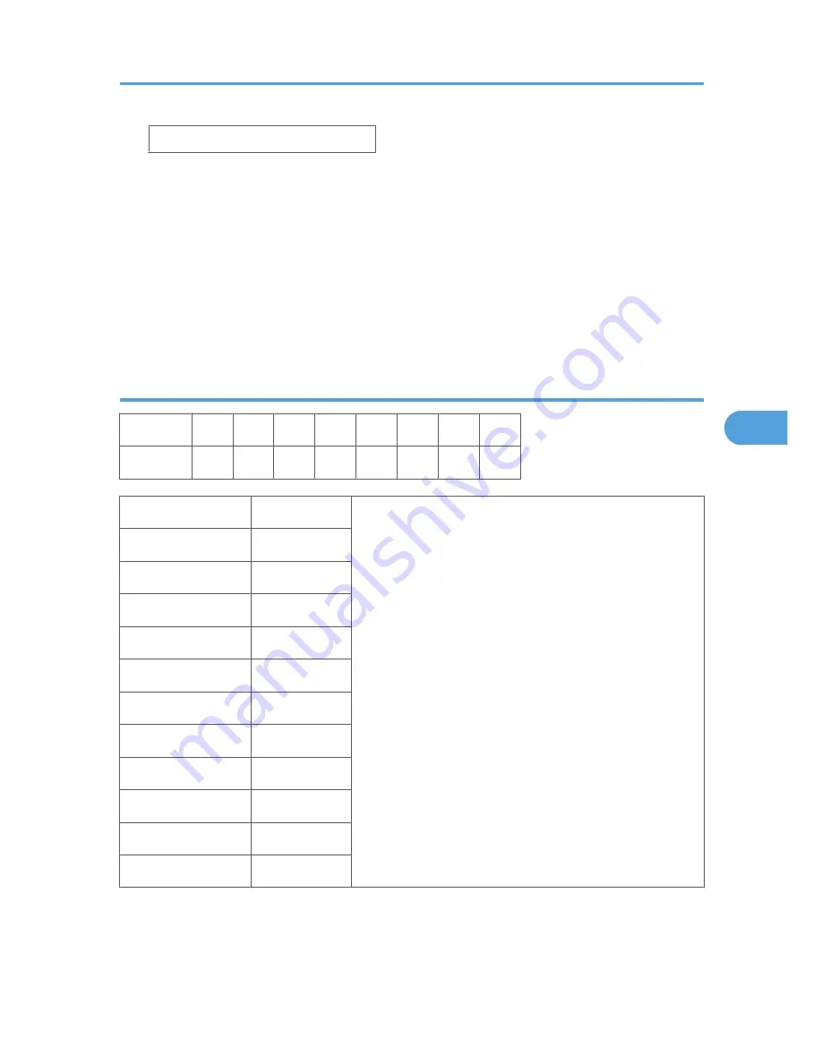
bit0 _
4.
Select the “0” or “1” for each position. The leftmost digit is 7 and the rightmost is 0.
• Press
or
to move the cursor to the right or left to position the it at the digit to change.
• Press [#Enter] then press
or
to toggle the digit between “1” and “0”.
• With the digit for entry displayed on the second line, press [#Enter]. The selected digit is entered
into the position above.
• Repeat this procedure to set all the digits.
5.
When you are finished, press [Escape] to return to the previous level. The new settings for
the bit switch are now stored.
Printer Controller Bit Switch Settings
Position:
7
6
5
4
3
2
1
0
Display:
0
0
0
0
0
0
0
0
Bit Switch 1
Default
Do not change these settings.
0
0
1
0
2
1
3
0
4
0
5
0
6
0
7
0
Bit Switch 2
All "0"
Bit Switch 3
All "0"
Bit Switch 4
All "0"
Service Program Mode Operation
183
5
Summary of Contents for A-P4
Page 1: ...Model A P4 Machine Code G147 SERVICE MANUAL May 12th 2006 Subject to change...
Page 27: ...Installation Flowchart 1 Installation 26 1...
Page 59: ...3 Reattach the application cover x1 1 Installation 58 1...
Page 65: ...2 Preventive Maintenance 64 2...
Page 72: ...Left Covers 1 Left upper cover A x4 2 Controller cover B x2 Covers and Common Procedures 71 3...
Page 82: ...Laser Unit 81 3...
Page 103: ...5 Cover C x2 6 Gear D x1 7 Lower paper feed unit E x2 x1 3 Replacement and Adjustment 102 3...
Page 128: ...Duplex Unit Duplex Cover Removal 1 Duplex unit cover A x4 Duplex Unit 127 3...
Page 181: ...4 Troubleshooting 180 4...
Page 289: ...Self Diagnostic Test Flow 5 Service Tables 288 5...
Page 306: ...Controller Block Diagram Board Layout 305 6...
Page 319: ...What Happens When a New Unit Is Detected 6 Details 318 6...
Page 367: ...6 Details 366 6...
Page 379: ...MEMO 378...
Page 380: ...MEMO 379...
Page 381: ...MEMO 380...


