Section 19
Controller Area Network (RCAN-TL1)
Rev. 0.50 May 18, 2006 Page 905 of 1588
REJ09B0313-0050
TTW[1:0]
Word
Word
Word
Trigger Time
Trigger Time
TT control
Tx-Trigger Time (Cycle Time)
Tx-Trigger Time (Cycle Time)
Offset[5:0]
rep_factor[2:0]
15
14
13
12
11
10
9
8
7
6
5
4
3
2
1
0
15
14
13
12
11
10
9
8
7
6
5
4
3
2
1
0
0
0
0
0
0
H'114 + N
*
32
H'116 + N
*
32
MB29 to 24
MB30
H'114 + N
*
32
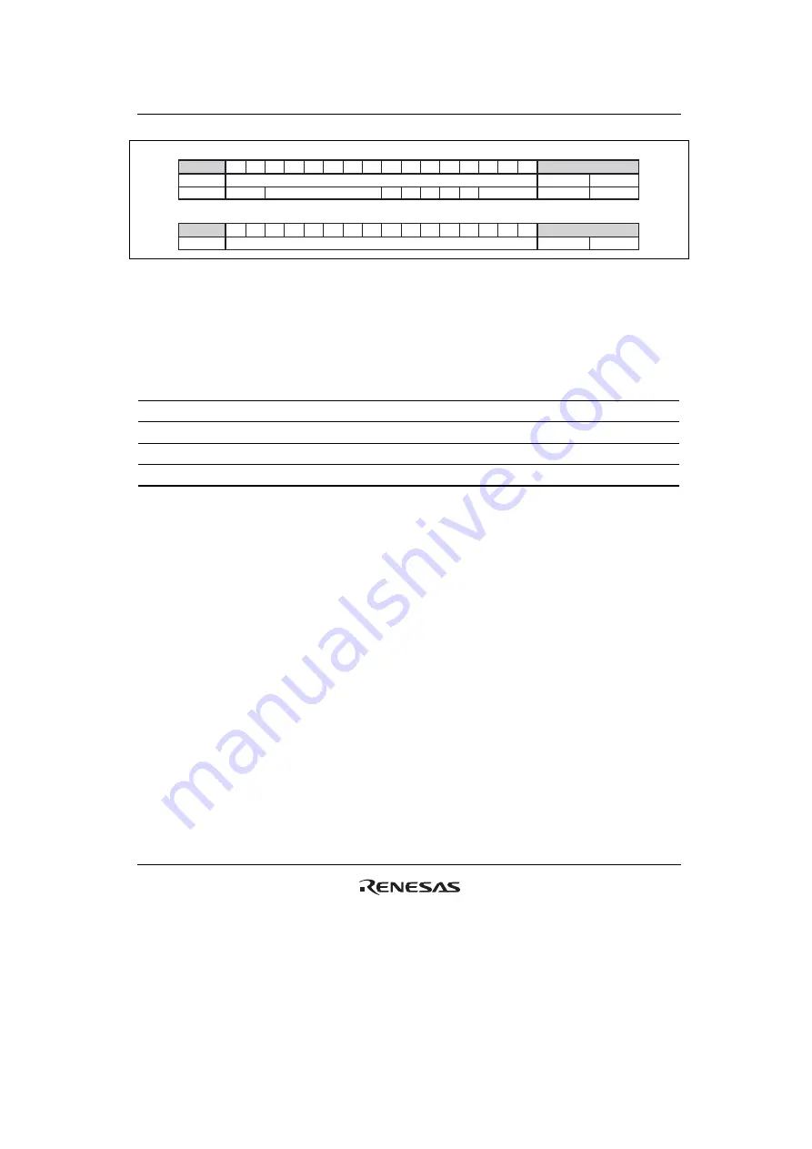
Figure 19.6 Tx-Trigger control field
•
TTW[1:0] (Time Trigger Window):
These bits show the attribute of time windows. Please
note that once a merged arbitrating window is opened by TTW = 2'b10, the window must be
closed by TTW = 2'b11. Several messages with TTW = 2'b10 may be used within the start and
the end of a merged arbitrating window.
TTW[1] TTW[0] Description
0
0
Exclusive window (initial value)
0 1 Arbitrating
window
1
0
Start of merged arbitrating window
1
1
End of merged arbitrating window
The first 16-bit area specifies the time that triggers the transmission of the message in cycle time.
The second 16-bit area specifies the basic cycle in the system matrix where the transmission must
start (Offset) and the frequency for periodic transmission. When the internal TTT register matches
to the CYCTR value, and the internal Offset matches to CCR value transmission is attempted from
the corresponding Mailbox. In order to enable this function, the CMAX (Cycle Maximum
Register) must be set to a value different from 3'b111, the Timer (TCNTR) must be running
(TTCR0 bit15 = 1), the corresponding MBC must be set to 3'b000 and the corresponding TXPR
bit must be set. Once TXPR is set by S/W, RCAN-TL1 does not clear the corresponding TXPR bit
(among Mailbox-30 to 24) to carry on performing the periodic transmission. In order to stop the
periodic transmission, TXPR must be cleared by TXCR. Please note that in this case it is possible
that both TXACK and ABACK are set for the same Mailbox if TXACK is not cleared right after
completion of transmission. Please refer to figure 19.7.
Summary of Contents for Single-Chip Microcomputer SH7203
Page 2: ...Rev 0 50 May 18 2006 Page ii of xxx ...
Page 30: ...Rev 0 50 May 18 2006 Page xxx of xxx ...
Page 52: ...Section 1 Overview Rev 0 50 May 18 2006 Page 22 of 1588 REJ09B0313 0050 ...
Page 98: ...Section 2 CPU Rev 0 50 May 18 2006 Page 68 of 1588 REJ09B0313 0050 ...
Page 128: ...Section 4 Clock Pulse Generator CPG Rev 0 50 May 18 2006 Page 98 of 1588 REJ09B0313 0050 ...
Page 200: ...Section 6 Interrupt Controller INTC Rev 0 50 May 18 2006 Page 170 of 1588 REJ09B0313 0050 ...
Page 242: ...Section 8 Cache Rev 0 50 May 18 2006 Page 212 of 1588 REJ09B0313 0050 ...
Page 400: ...Section 9 Bus State Controller BSC Rev 0 50 May 18 2006 Page 370 of 1588 REJ09B0313 0050 ...
Page 696: ...Section 13 Watchdog Timer WDT Rev 0 50 May 18 2006 Page 666 of 1588 REJ09B0313 0050 ...
Page 726: ...Section 14 Realtime Clock RTC Rev 0 50 May 18 2006 Page 696 of 1588 REJ09B0313 0050 ...
Page 876: ...Section 17 I2 C Bus Interface 3 IIC3 Rev 0 50 May 18 2006 Page 846 of 1588 REJ09B0313 0050 ...
Page 1054: ...Section 21 D A Converter DAC Rev 0 50 May 18 2006 Page 1024 of 1588 REJ09B0313 0050 ...
Page 1294: ...Section 24 LCD Controller LCDC Rev 0 50 May 18 2006 Page 1264 of 1588 REJ09B0313 0050 ...
Page 1386: ...Section 26 I O Ports Rev 0 50 May 18 2006 Page 1356 of 1588 REJ09B0313 0050 ...
Page 1512: ...Section 30 List of Registers Rev 0 50 May 18 2006 Page 1482 of 1588 REJ09B0313 0050 ...
Page 1598: ...Section 31 Electrical Characteristics Rev 0 50 May 18 2006 Page 1568 of 1588 REJ09B0313 0050 ...
Page 1606: ...Appendix Rev 0 50 May 18 2006 Page 1576 of 1588 REJ09B0313 0050 ...
Page 1618: ...Rev 0 50 May 18 2006 Page 1588 of 1588 REJ09B0313 0050 ...
Page 1621: ......
Page 1622: ...SH7203 Group Hardware Manual ...


