15
www.qualitrolcorp.com
5. Wire input sensors to the correct inputs, TB3 through TB10.
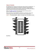
6. Connect the correct alarm control circuitry, TB1-2 through TB1-13 and TB1-18 through
TB1-32. See the wiring schematics or engineering drawings for your specific
transformer.
Note:
The optional heater input is TB1-1 and TB1-17.
Relay contact ratings: 10 A @ 115/230 VAC, 10 A @ 30 VDC
CAUTION:
The loops must be connected to an isolated analog input to avoid
potential damage to the 509ITM.
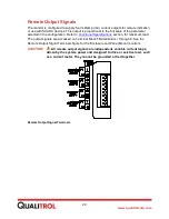
7. If required, connect the current output loops, TB2-1 through TB2-8.
8. Connect the RS-485 communications to TB2-9 through TB2-13.
•
4-wire:
TB2-9 through TB2-12; signal ground on TB2-13, not an earth ground (used
for DNP, Modbus, IEC 60870 and ASCII protocol communications).
•
2-wire RS485:
Used only for digital sensors (Hot Spot Modules, DGA sensors, etc.;
not for external communications). TB2-16 is not an earth ground
9.
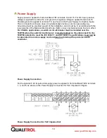
Connect the input power, TB1-14, 15, and earth ground to TB1-16.
•
Universal power supply:
100 - 240 VAC, 50/60 Hz
45 - 260 VDC
CAUTION:
Installing power outside of the recommended input range will
damage the unit.
10. Energize the 509ITM.
The monitor briefly
displays “Qualitrol” and the version of the board firmware.
Important:
The following operation can cause the alarm output state to change.
11. On the front panel, press
TEST
.
Relays 1 through 8 actuate.
Note:
Relays that have been configured with the test lockout feature enabled will not
operate, but the corresponding LED will light.
12. Upon commissioning the 509ITM, do the following steps to reset the maximum and
minimum values:
(a) Press
MENU
.
(b) Scroll to the View Maximum Value column (see menu flowchart).
(c) Press
RESET
.
(d) Scroll to the View Minimum Value column.
(e) Press
RESET
.
(f) Press
MENU
.
When the test is complete; the monitor defaults to the scrolling mode, cycling consecutively
through the display of each input. You are now ready to use the
Summary of Contents for 509ITM Series
Page 26: ...26 www qualitrolcorp com Current Input Wiring...
Page 55: ...55 www qualitrolcorp com 3 Continue with the setup procedure...
Page 101: ...101 www qualitrolcorp com...
Page 144: ...144 www qualitrolcorp com The following window will appear...
Page 167: ...167 www qualitrolcorp com The Customer Setup window displays 4 Click Load Tap Changer...
Page 178: ...178 www qualitrolcorp com Appendix...
Page 179: ......
Page 180: ......
Page 181: ......


