158
www.qualitrolcorp.com
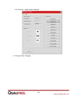
The
Calibrator - Signal Selection
window displays with the radio button for
Input 1
selected.
CAUTION:
Be extremely careful in the Calibrator tool. Changing calibration
values incorrectly might cause the 509ITM to malfunction.
4. Connect the ammeter (or multi-meter set to measure DC milliamps) to TB2 pins 1 and 2
with the positive probe on 1.
5. In the
Calibrator - Signal Selection
window, select the radio button for
Output 1
and click
[Calibrate].
The next two windows that appear are for calibrating the 0 - 1 mA section, which will
remain the same.
Summary of Contents for 509ITM Series
Page 26: ...26 www qualitrolcorp com Current Input Wiring...
Page 55: ...55 www qualitrolcorp com 3 Continue with the setup procedure...
Page 101: ...101 www qualitrolcorp com...
Page 144: ...144 www qualitrolcorp com The following window will appear...
Page 167: ...167 www qualitrolcorp com The Customer Setup window displays 4 Click Load Tap Changer...
Page 178: ...178 www qualitrolcorp com Appendix...
Page 179: ......
Page 180: ......
Page 181: ......


