19
www.qualitrolcorp.com
Power Supply
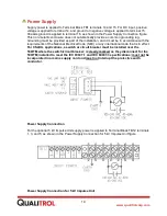
Supply power is applied to Terminal Block TB1 terminals 14 and 15. For DC input, positive
voltage is applied to terminal 14, and ground or negative voltage is applied to terminal 15.
Chassis ground is applied to terminal 16, as shown in the Power Supply Connection
figure
.
This non-metallic enclosure does not automatically provide a common grounding lug.
Grounding must be provided as part of the installation, and it must be in accordance with the
requirements of the National Electrical Code (NEC) or any international code that is in effect.
For CSA/UL applications, a switch or circuit breaker must be installed near the
509ITM where the switch/circuit breaker; is clearly marked as they disconnect for the
509ITM; installed to meet the IEC 60947-1 and IEC 60947-3 specifications; must not be
incorporated in a mains supply cord and must not interrupt the protective earth
conductor.
Power Supply Connection
For the optional 5 kV Impulse Unit supply power is applied to Terminal Block TB12 terminals
1, 3, and 5, as shown in the Power Supply Connection for 5 kV Impulse Unit figure.
Power Supply Connection for 5 kV Impulse Unit
Summary of Contents for 509ITM Series
Page 26: ...26 www qualitrolcorp com Current Input Wiring...
Page 55: ...55 www qualitrolcorp com 3 Continue with the setup procedure...
Page 101: ...101 www qualitrolcorp com...
Page 144: ...144 www qualitrolcorp com The following window will appear...
Page 167: ...167 www qualitrolcorp com The Customer Setup window displays 4 Click Load Tap Changer...
Page 178: ...178 www qualitrolcorp com Appendix...
Page 179: ......
Page 180: ......
Page 181: ......


