172
www.qualitrolcorp.com
Verifying the Calibration
1. Re-enter the Customer
−
Setup tool.
2. Click
File > Print Preview
.
3. Scroll to page 5 of the Configuration Table.
The tap position numbers will be on the left side of the page with the corresponding
calibration values in parentheses. These values should range from 0.00 - 1.00 in
approximately equal increments.
4. If the calibration values are not correct, check the wiring and recalibrate the Tap Position
Resistor Bridge to the input module.
5. Verify the calibration by moving the Load Tap Changer to various tap positions and
checking the local display for matching tap positions.
Summary of Contents for 509ITM Series
Page 26: ...26 www qualitrolcorp com Current Input Wiring...
Page 55: ...55 www qualitrolcorp com 3 Continue with the setup procedure...
Page 101: ...101 www qualitrolcorp com...
Page 144: ...144 www qualitrolcorp com The following window will appear...
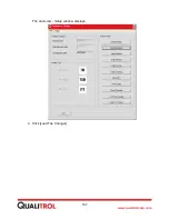
Page 167: ...167 www qualitrolcorp com The Customer Setup window displays 4 Click Load Tap Changer...
Page 178: ...178 www qualitrolcorp com Appendix...
Page 179: ......
Page 180: ......
Page 181: ......


