


PRONAR Sp. z o.o.
17-210 NAREW, UL. MICKIEWICZA 101A, PODLASKIE PROVINCE
phone:
+48 085 681 63 29
+48 085 681 64 29
+48 085 681 63 81
+48 085 681 63 82
fax:
+48 085 681 63 83
+48 085 682 71 10
www.pronar.pl
OPERATOR'S MANUAL
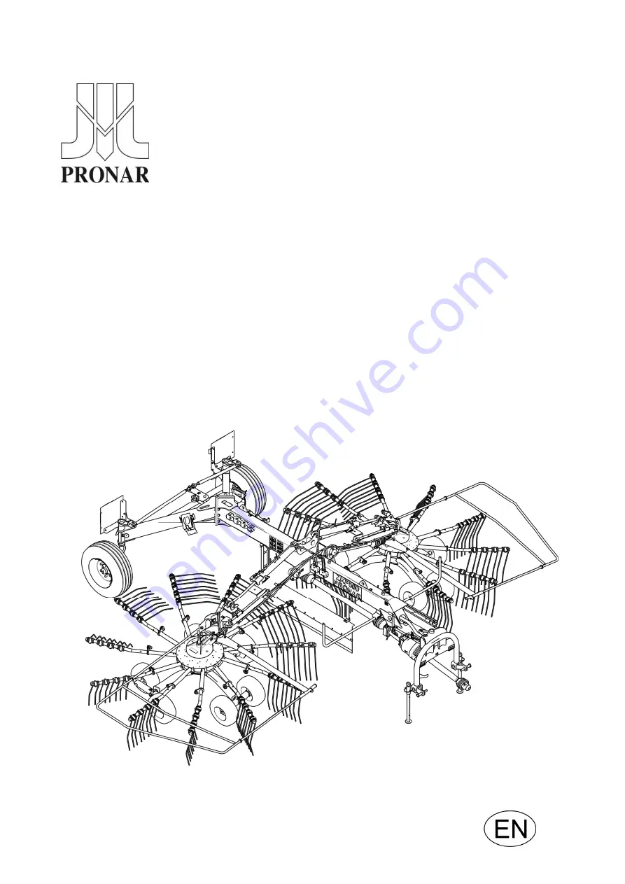
ROTARY RAKE
PRONAR ZKP800
TRANSLATION OF THE ORIGINAL INSTRUCTIONS
EDITION 1C-09-2016
PUBLICATION NO 231N-00000000-UM
Summary of Contents for ZKP800
Page 2: ......
Page 3: ...ROTARY RAKE PRONAR ZKP800 MACHINE IDENTIFICATION TYPE ZKP800 SERIAL NUMBER ...
Page 7: ......
Page 8: ......
Page 12: ......
Page 13: ...SECTION 1 BASIC INFORMATION ...
Page 24: ...Pronar ZKP800 SECTION 1 1 12 ...
Page 25: ...SECTION 2 SAFETY ADVICE ...
Page 38: ...Pronar ZKP800 SECTION 2 2 14 FIG 2 2 Locations of information and warning decals ...
Page 39: ...SECTION 3 DESIGN AND OPERATION ...
Page 49: ...SECTION 4 CORRECT USE ...
Page 69: ...SECTION 5 MAINTENANCE ...
Page 85: ...SECTION 5 Pronar ZKP800 5 17 FIG 5 5 Rotary rake lubrication points ...
Page 86: ...Pronar ZKP800 SECTION 5 5 18 FIG 5 6 Rotary rake lubrication points ...
Page 93: ...NOTES ...
Page 94: ... ...
Page 95: ...ANNEX A FIRST ASSEMBLY MANUAL ...