- 19 -
2) LCD
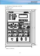
It shows EPIC-R300’s measuring, setting, stored information, and search information.
It is convenient 20*4 character module LCD to move the screen through controling
manipulation button.
3) System Communication LED
LED which shows communication state when EPIC-R300 communicates with host system.
- RX LED : Receiving
- TX LED : Transmitting
- RTS LED : Request transmission to Modem
4) ALT SET Button
Button which select function group. LED on,
EPIC-R300
’s operate by primary group. LED
off, by reverse group.
5) Manipulation Button
Button which controls LCD screen.
- Menu(M) Button : Button which moves to upper menu
- Up(▲) Button : Button which increases set value or moves the menu upwards
- Down(▼) Button : Button which decreases set value or moves the menu downwards
- Enter(
⤶
) Button : Button which enters the menu or saves set value
6) Distribution Fault Status LED
LED which shows fault on Distribution Line. It shows distribution line’s source and whether
i
t is load’s voltage, and whether it is synchronous.
- Live Source LED : LED which shows whether it supplies voltage on source side
- Live Load LED : LED which shows whether it supplied voltage on load side
- Phase Sync. Fail LED : LED which shows synchronous fail of phase A/R or B/S or C/T voltage
- Phase A/B/C Loss LED : LED which show phase loss of phase A/B/C on source side
- Phase R/S/T Loss LED : LED which show phase loss of phase R/S/T on load side
- Phase A LED : A Phase Fault LED
- Phase B LED : B Phase Fault LED
- Phase C LED : C Phase Fault LED
- Phase N LED : N Phase Fault LED
- Phase SEF LED : Zero Phase Fault LED on Non-Ground System
- Recloser Ready LED : LED which shows recloser and a control are ready to start a new
auto-reclosing sequence
- Recloser Cycle LED : LED which shows reclosing sequence is in progress
- Recloser Lockout LED : LED which shows recloser goes to lockout with open
- Trip Info Min LED : LED which shows the measured phase current is over the set
minimum operating current
- Trip Info Volt LED : LED which shows the recloser operates by voltage protection
elements
Summary of Contents for RECLOSER
Page 1: ...User Manual Document Version 1 5 Feb 28 2019 http powersys kr http www powersys kr...
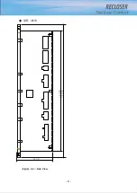
Page 14: ...8 3 5 Mechanical Performance and Size Weight 3 5 kg FRONT VIEW Figure 3 1 Front View...
Page 15: ...9 SIDE VIEW 343 00 310 00 91 00 Figure 3 2 Side View...
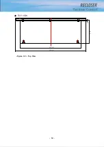
Page 16: ...10 TOP VIEW 84 0 260 0 225 0 1 0 0t Figure 3 3 Top View...
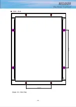
Page 17: ...11 REAR VIEW 180 0 120 0 Figure 3 4 Rear View...
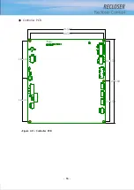
Page 22: ...16 Controller PCB 215 00 103 90 121 10 112 50 112 50 235 00 205 00 Figure 3 8 Controller PCB...
Page 69: ...63...
Page 71: ...65 Example configuration file...
Page 73: ...67 2 TC Curve 1 4 100 101 10 1 100 101 102 Time sec Current In Multiplies of Setting 1 2 3 4...
Page 74: ...68 3 TC Curve 5 8 100 101 10 1 100 101 102 Time sec Current In Multiplies of Setting 5 6 7 8...
Page 77: ...71 6 TC Curve A D 100 101 10 1 100 101 102 Time sec Current In Multiplies of Setting A B C D...
Page 78: ...72 7 TC Curve E M 100 101 10 1 100 101 102 Time sec Current In Multiplies of Setting E K L M...
Page 79: ...73 8 TC Curve N T 100 101 10 1 100 101 102 Time sec Current In Multiplies of Setting N P R T...
Page 80: ...74 9 TC Curve V Z 100 101 10 1 100 101 102 Time sec Current In Multiplies of Setting V W Y Z...

