- 47 -
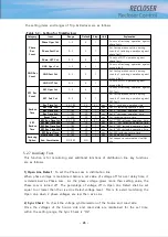
perfoms protecton operation and the load in the lower side of protection devise will
experience a power outage. Thus, the blackout range of the distribution line are spread
to normal condition section as well as fault occurrence section.
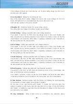
For coping with those case, loop control function will operate in the way of separating the
fault section, and supplying power to normal section, then it helps to minimize the outage
time.
EPIC-R300 provides those loop control function which is operable in service only by using
the information about voltage, current, and operating state.
Depending on the configuration of recloser being installed, 3 modes of loop control can
be selected.
- Feeder recloser
: the recloser is installed near the substation or inside.
- Midpoint recloser
: installation point is between feeder recloser and tie recloser.
- Tie-point recloser
: the recloser are usually installed at tie point where two distribution
lines are interconnected.
1) feeder recloser
Protection elements are generally operate when downstream fault occurs in the distribution
line. If it detects voltage loss at power supply, recloser will trip after set time.
In both cases that trip by protection elements and remote operation, loop control function
is automatically stopped.
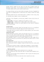
2) Mid point recloser
Protection elements are generally operate when downstream fault occurs in the distribution
line. If, due to the action at power source side, it detects voltage loss at both sides, it
shall be automatically changed into another setting group after set time.
After downstream recloser or tie point recloser’s operation, the power supply starts to
provide from reverse side. For this moment, the reclosing action shall be hold for a certain
period of time.
3) Tie-point recloser
When voltage loss is detected in the set side, it close after the set time.
After closing, when the fault is detected, it stops and holds reclosing for a sertain period
of time.
The operation by protection elements is possible after normalization of reclosing element.
The activated operation group shall be changed according to feeding direction or setting
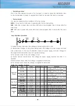
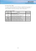
- “Dead bus open time”
The loop automation operates when the distribution line is in dead state.
It can be determined by using setting value based on voltage whether distribution line is
dead or not.
The state of loop automation shall be determined as “dead” only when the dead bus state
is maintained for a set time.
The voltage values of all sources and load side shall not exceed the set values.
Summary of Contents for RECLOSER
Page 1: ...User Manual Document Version 1 5 Feb 28 2019 http powersys kr http www powersys kr...
Page 14: ...8 3 5 Mechanical Performance and Size Weight 3 5 kg FRONT VIEW Figure 3 1 Front View...
Page 15: ...9 SIDE VIEW 343 00 310 00 91 00 Figure 3 2 Side View...
Page 16: ...10 TOP VIEW 84 0 260 0 225 0 1 0 0t Figure 3 3 Top View...
Page 17: ...11 REAR VIEW 180 0 120 0 Figure 3 4 Rear View...
Page 22: ...16 Controller PCB 215 00 103 90 121 10 112 50 112 50 235 00 205 00 Figure 3 8 Controller PCB...
Page 69: ...63...
Page 71: ...65 Example configuration file...
Page 73: ...67 2 TC Curve 1 4 100 101 10 1 100 101 102 Time sec Current In Multiplies of Setting 1 2 3 4...
Page 74: ...68 3 TC Curve 5 8 100 101 10 1 100 101 102 Time sec Current In Multiplies of Setting 5 6 7 8...
Page 77: ...71 6 TC Curve A D 100 101 10 1 100 101 102 Time sec Current In Multiplies of Setting A B C D...
Page 78: ...72 7 TC Curve E M 100 101 10 1 100 101 102 Time sec Current In Multiplies of Setting E K L M...
Page 79: ...73 8 TC Curve N T 100 101 10 1 100 101 102 Time sec Current In Multiplies of Setting N P R T...
Page 80: ...74 9 TC Curve V Z 100 101 10 1 100 101 102 Time sec Current In Multiplies of Setting V W Y Z...

