- 20 -
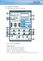
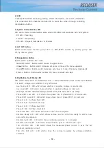
- Trip Info Freq LED : LED which shows the recloser operates by frequency protection
elements
- Power flow LED(Reverse) : LED which shows whether forward or reverse power
flow
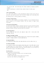
7) Non Reclosing Button
It is used to set whether to allow auto-reclosing sequence after the trip due to
overcurrent and protection elements. Push the button to toggle current functionality. When
the indicator turns on, reclosing operation is restricted.
8) Protection Blocked Button
It is used to restrict operation of all protection elements. It can be temporarily used to
restrict operation of all protection elements. Push the button to toggle current
functionality.
9) Ground Trip Blocked Button
It is used to set whether operation of protection elements for ground overcurrent and SEF.
Push the button to toggle current functionality. When the indicator turns on, operation of
protection elements for ground overcurrent and SEF is restricted.
10) Fault Reset Button
It is a button to reset fault and diagnosis signal LED. It reset actual fault
information with LED.
11) Battery Test Button and LED
It is a button to test battery and battery charger circuit. It shows the test result on Battery
Low LED. If battery low LED is on, which means test fail.
12) Lamp Test Button
It is a button to test LEDs. When push lamp test button, all of the LEDs are turn on.
13) Control Lock Button
It is a button to prevent control operation when doing open / close REC switch on local
or remote when turn on control lock LED. If the control lock LED is on, the protection
fun
ction of Recloser also becomes locked. Push control lock button to turn off control lock
LED and then use open / close button to operate.
14) Hot Line Tag
When Activating hot line tag function
- Operation of all protection elements is set to be single shot mode.
- It operates by fast curve.
- It restricts closed operation for the recloser from all sources.
- Tag can be only removed by the tagging source.
Summary of Contents for RECLOSER
Page 1: ...User Manual Document Version 1 5 Feb 28 2019 http powersys kr http www powersys kr...
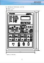
Page 14: ...8 3 5 Mechanical Performance and Size Weight 3 5 kg FRONT VIEW Figure 3 1 Front View...
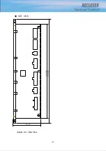
Page 15: ...9 SIDE VIEW 343 00 310 00 91 00 Figure 3 2 Side View...
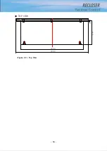
Page 16: ...10 TOP VIEW 84 0 260 0 225 0 1 0 0t Figure 3 3 Top View...
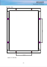
Page 17: ...11 REAR VIEW 180 0 120 0 Figure 3 4 Rear View...
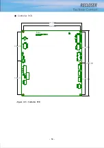
Page 22: ...16 Controller PCB 215 00 103 90 121 10 112 50 112 50 235 00 205 00 Figure 3 8 Controller PCB...
Page 69: ...63...
Page 71: ...65 Example configuration file...
Page 73: ...67 2 TC Curve 1 4 100 101 10 1 100 101 102 Time sec Current In Multiplies of Setting 1 2 3 4...
Page 74: ...68 3 TC Curve 5 8 100 101 10 1 100 101 102 Time sec Current In Multiplies of Setting 5 6 7 8...
Page 77: ...71 6 TC Curve A D 100 101 10 1 100 101 102 Time sec Current In Multiplies of Setting A B C D...
Page 78: ...72 7 TC Curve E M 100 101 10 1 100 101 102 Time sec Current In Multiplies of Setting E K L M...
Page 79: ...73 8 TC Curve N T 100 101 10 1 100 101 102 Time sec Current In Multiplies of Setting N P R T...
Page 80: ...74 9 TC Curve V Z 100 101 10 1 100 101 102 Time sec Current In Multiplies of Setting V W Y Z...

